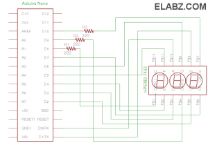
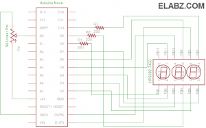
Arduino Nano and HP5082-7433 vintage 7-segment LED display
I have to admit, I created this 7-segment display project not because I needed a visual output for my next Arduino project but simply because I have a really soft spot for those whimsical big-eyed miniature LED displays. Some 20+ years ago I have hand-soldered hundreds of these little displays at one of my first jobs and seeing these displays come to life was always a big relief – it meant that the device was working. But I digress…
{adinserter Internal_left}In any case, despite the fact that these HP5082-7433 LED displays are rather hard to come by these days, they are still available from online sources such as eBay and they are a great match for any MCU-based project that requires visual output, especially indoors. They pack 3 digits that are big enough to be seen from anywhere on the desk and yet fit inside a breadboard-friendly DIL-12 package (15.37mm x 6.35mm). They are very easy to drive due to the very small forward currents and the rest of this post is about how to do just that
You can see more data about the part in the HP5082-7432/7433 7-segment LED Display Datasheet but some of the most important data is the current needed to light a segment – given the right ambient light, you can see the output at 250μA . It’s therefore not a surprize that these little displays were used in watches and battery-powered calculators back in their heyday. It means that the highest load digit – “8” – will only draw 3.25mA and you can both source and sink enough current from Arduino Nano’s digital output without overloading the Arduino.
One of the important features of this circuit was going to be its simplicity and therefore some sacrifices were made. For example, you would normally have 8 current limiting resistors, one for each segment anode. That would make each segment’s current equal to that of the next which, in turn, will make all digits equally bright. In this case I only used 3 resistors – one for each common cathode. All anodes comprising one digit therefore share one limiting resistor and so the digit “8” that has 7 segments is less bright than digit “1” that has only two. Also, the 220Ω limiting resistor is only working properly with digits having 5,6 or 7 segments. The rest of the digits are having their segments lit with currents higher than needed. So, you’re welcome to improve this circuit by eliminating the 220Ω current limiting resistors in the common cathode lines and use 8 (7 if the digital point is not used) 510Ω + in the anode lines instead.
One other characteristic of this circuit is the large number of Arduio’s output lines used. Nano has 14 digital outputs. From those we are using 8 for the anodes (even though the digital point is not used in the software I include here – another improvement direction) and 3 for the cathodes. So, there are 3 digital outputs left for either activating other types of outputs or making a 6-digits display by adding the second HP5082-7433 if all the rest of Arduino connections in this project are inputs.
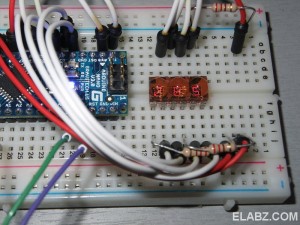
So, to finish with the hardware part of the project, here is how the breadboard looks like (left). It’s a pretty simple circuit that can be thrown together in 5 minutes or less.
Now to the software part. There are two different sketches attached here – one is for the simplest circuit that has no inputs whatsoever and only counts from 0 to 999 (in a loop). The other one is for the circuit with a 5KΩ linear potentiometer which has its wiper (middle contact) connected to Arduino’s Analog Input 0 and its other contacts to ground and +5V respectively.
Arduino sketch for counter using 3-digit 7-segment LED display with common cathode
Arduino sketch for outputting analog read value to a 3-digit 7-segment LED display
Basically, the heart of the code is the show(value) subroutine. You can copy it into your own program and call it every time you need to output a 3-digit decimal value. The code can be adapted to showing hexadecimal values by adding few more encoding values (for digits A-F) to the digits array. Decimals only are coded here:
byte const digits[]={
B00111111,B00000110,B01011011,B01001111,B01100110,B01101101,B01111101,B00000111,B01111111,B01101111
};
Please note that the cathodes are hooked up to digital outputs D8,9 and 10 in the reverse order. D8 is cathode 3 and D10 is cathode 1. If you have different digital outputs used, don’t forget to change this line:
int digit_common_pins[]={8,9,10};
I’ve seen several implementations of seven segment output using Arduino and many are using delay() function to light the current digit long enough for the eye to register before moving to the next. I think it’s pretty unfortunate because during that time Arduino cannot do anything else – cannot scan buttons or read analog values because it’s essentially paused. In my code I made sure that the scanning functionality does not actually lock the processor up for the duration of the cycle. It’s then free to service all the other functional elements of your project.
Here is the full code of the program reading the analog value and outputting it in 3-digit decimal version:
/*
ELABZ.COM
Directly Driving a small 7-segment LED display with Arduino. Tested on vintage HP5082-7433 micro LED displays
A sample Arduino sketch by http://elabz.com
 Pin assignments:
 ANODES:
 D0 - a
 D1 - b
 D2 - c
 D3 - d
 D4 - e
 D5 - f
 D6 - g
 D7 - dp (digital point)

    a
  ********
  *      *
f *      * b
  *  g   *
  ********
  *      *
e *      * c
  *  d   *
  ******** # dp

 CATHODES:
 D8 - cathode 3
 D9 - cathode 2
 D10 - cathode 1
 */

byte const digits[] = {
B00111111,B00000110,B01011011,B01001111,B01100110,B01101101,B01111101,B00000111,B01111111,B01101111};
int digit_common_pins[]={8,9,10};
int analogPin = 0;
int val=0;
int refresh_delay = 5;
int count_delay = 100; // COUNTING SECONDS IF count_delay = 1000
long actual_count_delay = 0;
long actual_refresh_delay = 0;
int increment = 0;
int max_digits =3;
int current_digit=max_digits-1;
int increment_max = pow(10,max_digits);

void setup(){

  DDRD = B11111111;

  for (int y=0;y<max_digits;y++)
  {
    pinMode(digit_common_pins[y],OUTPUT);
    digitalWrite(digit_common_pins[y], HIGH);
  }


}

void loop() {


  if(millis() - actual_count_delay > count_delay)

  {
    actual_count_delay = millis();

    val = analogRead(analogPin);    // read the input pin

  }

  show(val);

}

void show(int value) {
  int digits_array[]={};
  int y=0;
  boolean empty_most_significant = true;


  if(millis() - actual_refresh_delay >= refresh_delay)
  {

  for (int z=max_digits-1;z>=0;z--)
  {


    digits_array[z] = value / pow(10,z); //rounding down by converting from float to int

    if(digits_array[z] != 0 ) empty_most_significant = false;  // DON'T SHOW LEADING ZEROS

    value = value - digits_array[z] * pow(10,z);


   if(z==current_digit)
   {
    if(!empty_most_significant || z==0){ // DON'T SHOW LEADING ZEROS EXCEPT FOR THE LEAST SIGNIFICANT
      PORTD = digits[digits_array[z]];
    }else{
      PORTD = B00000000;
    }


     digitalWrite(digit_common_pins[z], LOW);
   }else{
     digitalWrite(digit_common_pins[z], HIGH);
    }

}


      current_digit--;
      if(current_digit < 0)
      {
        current_digit= max_digits; // NEED AN EXTRA REFRESH CYCLE TO CLEAR ALL DIGITS
      }

 actual_refresh_delay =  millis();
 }

}


[…] « Arduino Nano and HP5082-7433 vintage 7-segment LED display […]
Thanks for stopping by my blog and offering your suggestion (with link to here) on avoiding the use of delays when working with multi-digit 7-segment displays.
The vintage display is certainly cool. I got a couple in a grab bag I bought from Jameco. Good stuff.
Hey, your WP syntax highlight plugin looks awesome!
Hi and thank you for sharing!
I’ve seen in many schems of arduino driving a 3(or more) 7 segment display and the majority, if not all, included mosfet diver to the display. So why yours don’t have?
cheers
kik
Hi, the reason this schematics does not include a driver for the LED display is simply because the display is so small (size and current-wise), Arduino is able to drive it directly from the I/O pins