ATtiny13 POV display: same hardware, different message
St. Patrick’s Day is coming up and I thought it’s already time to update the original Valentine’s Day POV display with a new message and make use of the second PCB I had done at BatchPCB. Also, fortunately, John “smeezekitty” (the author of the Attiny13 core used for programming it in Arduino IDE) stopped by my blog and pointed out to an issue with the original firmware, which prompted me to take another hard look at it and the result has been a saving of whopping 20 or so bytes – it was just enough to fit the word “BEER” which, as I mentioned in the original post, we did not have any space in flash left for. Well, now we do and below is the new software
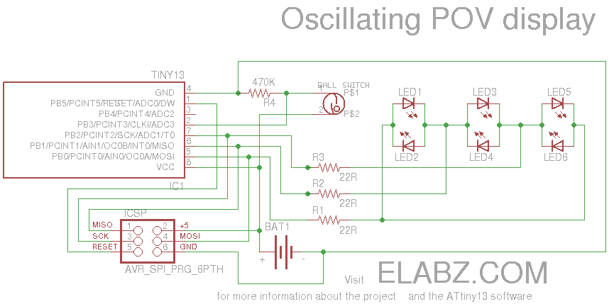
Oscillating POV display circuit diagram
I have tried to comment as much of the code as I could in case you are making adjustments.
There’s still some space for an even longer message now although it’s getting really hard to fit them into the physical space now – since this is an oscillating POV display, you are limited by the path your arm is plotting while going back and forth – it’s probably only about a foot (30 cm) before it starts looking like a pretty vigorous cardio exercise 🙂 In other words it’s very unlikely that it’s going to be very convenient to swing a POV display with “I ❤ HOMEWORK” even though there’s probably just enough memory left in Attiny13 to fit it all in.
OK, enough talk, here is the new code with the “I ❤ BEER” message.
POV display on Attiny13 – I HEART BEER message
Cheers!
Hi,
I have try to make your “skaky POV” this weekend.
I have use the µC I have : ATTINY85.
I believe that the way to do interrupts on ATTINY85 is different on ATTINY13… It can explain my failure…
Can you explain me a little more the usage you made of the external interrupt on your code ?
In your source code I see were you enable interrupts
(
sbi(GIMSK,PCIE); // Turn on Pin Change interrupt
sbi(PCMSK,PCINT3); // Which pins are affected by the interrupt
)
but I don’t understand the action that are linked to this external interrupt.
Do you think it is possible to do the same thing with “pure arduino instruction” like attachInterrupt() ?
I think the interrupt implementation is the same in ATtiny85 (although I have to admit I haven’t checked yet). The sleep mode functions set_sleep_mode(), sleep_mode() come from an external library called sleep.h – make sure your sketch has it included in the beginning. As far as action linked to the interrupt – there is no special function linked (one reason not to use attachinterrupt() ) – because nothing should be happening before the interrupt occurs, so the linked action is essentially the main loop. Until the interrupt comes, the MCU sleeps and executes no code whatsoever.
Another reason I did not use attachinterrupt() was that I was not sure if the function was implemented in the Attiny13 core I’ve used for compiling the sketch. It may be there, actually, I just didn’t look because there was an alternative way to do the sleep without relying on the feature. When I had just started smeezkitty’s ATtiny13 core, it had only the bare essentials in it. I know that John had done more work on it and it’s more “polished” now – perhaps the function is there by now. But, nevertheless, since you’re using a different MCU and therefore a different core, the standard attachInterrupt() may be implemented there. In fact, I’d be surprised if it’s not in the MIT core for ATtiny85.
Thanks for stopping by my blog!
Thanks you for your anwser.
I think I have understood the usage you make of interupts.
But after tring several setups (software and hardware), I haven’t reach a functional state. Maybe it’s due to my tilt sensor.
Can you tell me if you are using a tilt sensor like this one : http://www.ebay.com/itm/370516344093?ssPageName=STRK:MEWNX:IT&_trksid=p3984.m1439.l2649 ?
Best regards
Phil
The sensor itself is fine, I’ve used exactly the same. They are incredibly simple devices – just a small metal ball bouncing around a metal cylinder with another isolated metal contact at one end. Take a look at the way the switch is hooked up – perhaps it’s missing a pull-up resistor? Maybe you’re connecting to a different pin on Attiny? You can also temporarily replace it with just a pushbutton and see if the LEDs start to blink very rapidly after you press it.
Wow this is a really nice job what you have done here. I like the idea with the tilt sensor. Anyway, how could I find out how I can print out other letters than “r, i, l, o, v, e and b”? Is there enough space to add them to the code? br Dan
Hi Dan, yes, I think you can fit 7 letters in there, although it will be tough. The I ❤ BEER message has 6 but the heart symbol ❤ is very wide compared to the others. You normally need 4-5 bytes per letter (including the space character separating the letters) but the heart symbol takes 8. The sketch, with the I ❤ BEER message compiles to 1016 bytes out of available 1024, so you still have 8 bytes left. Here is the piece of the code that’s responsible for the actual message. Note that the message is presented as one continuous display, 8 dots high by 30 dots long. If you add 8 bytes of memory, it will be 38 dots long. If a letter is occurring more than once, you still have to use memory space to spell out the second instance, so there’s no saving in having multiple occurrences of the same letter. Anyway, I think the code below is self-explanatory, but if you have more questions, shoot.
/*St. Patrick's Day message */ PROGMEM byte column[30] = { 33, // --X----X // 0 63, // --XXXXXX // 1 33, // --X----X // 2 0, // -------- // 3 24, // ---XX--- // 4 60, // --XXXX-- // 5 30, // ---XXXX- // 6 15, // ----XXXX // 7 30, // ---XXXX- // 8 60, // --XXXX-- // 9 24, // ---XX--- // 10 0, // -------- // 11 63, // --XXXXXX // 12 41, // --X-X--X // 13 41, // --X-X--X // 14 22, // ---X-XX- // 15 0, // -------- // 16 63, // --XXXXXX // 17 41, // --X-X--X // 18 41, // --X-X--X // 19 0, // -------- // 20 63, // --XXXXXX // 21 41, // --X-X--X // 22 41, // --X-X--X // 23 0, // -------- // 24 63, // --XXXXXX // 25 44, // --X-XX-- // 26 42, // --X-X-X- // 27 17, // ---X---X // 28 0 // -------- // 29 };Thank you for answering so fast, what I don´t understand is why for example
stands for two LED
What would be for example 25? oder how can I assign the x to other numbers? Is there a scheme for all possibilities or a trick to calculate?
DaN, that is simply binary code: decimal 24 written in binary (8-bit) would look like this 00011000 . Basically, the two LEDs with I/O number in Port B that corresponds to the “1”s will be ON. The rest of the LEDs, represented by “0”s, will be OFF. This becomes one vertical column of dots, and each character needs about 4-5 of them (including the one column in which all LEDs are OFF – the space between the characters).
Hope this helps
Oh now it makes sense 🙂 Thank you a lot!