Serial OLED display and Arduino – a perfect combination
Enter the serial LCD Alternative – Seetron 4-line, 16-character Serial OLED Display which I recently had an opportunity to work with, thanks to Scott of Scott Edwards Electronics Inc., the manufacturer of this great device.
I will be using the display in a couple of projects I’m working on but I could not resist to check it out as soon as possible and that’s how the demo application you see below came about
The serial OLED display is incredibly easy to integrate into an Arduino-based project. On the hardware side it requires only three connections: the ground, the +5V power and the signal connector that gets connected to Arduino’s Tx (D1) output. In fact, Seetron makes a BSW-CBL wiring harness that’s specifically designed for breadboards and it would not be an overstatement to say that I had a working hardware part of the project ready in less than 5 minutes!
{adinserter Internal_left}Another great advantage of the OLED display should be apparent on the picture and the video above: an extremely bright and high-contrast screen, very easily read in any lighting condition. I’ve been playing with electronics for a long time and so my stock tends to have older parts in it. So, this was the first OLED display I had an opportunity to work closely with and I’d say that it reads better than my previous personal favorite display type – VFD (Vacuum fluorescent display). However, unlike VFDs, this OLED display does not require high voltage power supply and can be easily supplied from Arduino’s on-board +5V voltage regulator.
To even further enhance readability, you can use one of the larger fonts, also selectable via the serial interface. The demo application here uses one of those larger fonts – 2×16 characters and there are six fonts in total – from the standard 4 lines by 16 characters to the huge 1 line of 4 characters. You can also upload up to 16 of your own custom characters and you can save a particular screen to be used as the start-up splash screen instead of the default “GLO-416Y V1.0 seetron” screen. All these enhancements and all other control of the output is done via the serial interface, so please read the serial OLED display programming guide for more information.
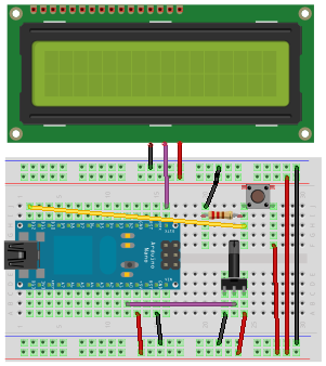
Since there are only three more parts in the entire circuit, I decided to employ Fritzing (I’m still learning it, hence the quality of the illustration) and draw a visual representation of the breadboarded circuit rather than a schematic diagram, on left. Despite the learning curve I liked the software so much that you’ll definitely see more of those visual project pages in the future …The black part to the right of Arduino Nano on this diagram is a potentiometer. Its wiper (middle contact) is connected to Arduino’s Analog 0 input the the value from 0 (0V) to 1023 (+5V) is then read on the OLED display. The potentiometer can be of any value, really. I used 5kΩ The push button is connected between the Arduino’s D12 input and +5V. When the button is not pushed, D12 is tied down to GND with a 10kΩ resistor.
The simple circuit has its own disadvantages, of course. One of them is that the display is connected to the same Tx output that’s being used during the communication with PC when you upload a new Arduino firmware. If the display is already on, it picks up some garbage from the serial communication which was not intended for the display. This should not be a problem with a real world application though because you only upload the code once and the rest of the time the display has Tx to itself all the time.
One of the most interesting features of Seetron’s serial OLED is its ability to turn off the OLED driver via the serial interface by issuing a Ctl-O (0x0F HEX) command. The display turns off but the serial interface is still on, and you can then issue the Ctl-N (0x0E HEX) to turn it back on. There is a significant difference in the current that the display consumes – I’ve measured approx 48mA in ON and only 6mA in OFF mode. Additionally, although it’s really hard to see on the video due to the lighting conditions while I was shooting it, but you can actually still see the content of the display after the driver has been turned off. You cannot change the content until you turn it back on of course, but if your screen updates infrequently, I think this could be used to conserve some battery power – only turn the driver on when you need to change the screen, then turn it off.
All in all, Seetron’s 4×16 serial OLED display is a great addition to any Arduino project that needs a text display. Its output is superb in any lighting condition, it easily integrates with Arduino both in terms of hardware, power supply as well as software, and it requires very little additional code (see the example below) so you can concentrate on writing the code for your application, not the display.
Sample application #1
This application reads and outputs voltage (in values from 0 to 1023) on the wiper of the potentiometer and turns the display driver on/off when a pushbutton on D12 is pressed. An even simpler application follows below.
/*
ELABZ.COM
A demonstration sketch for driving a serial  OLED
display by seetron.com - GLO-416Y or GLO-216Y/G
*/
const int analogPin = 0; // Read voltage on analog pin 0
const int buttonPin = 12; // Push button on digital pin 12
const int ledPin =  13; // LED on digital pin 13 to indicate button state. It should already be connected on the Arduino board.
int val=0; // Actual value read between 0 and 1023
const int refresh_delay=500; // refresh display reading every refresh_delay milliseconds
long actual_refresh_delay = 0; //actual time in ms since the beginning of refresh cycle
int reading = LOW;
int buttonState; // current push button state
int lastButtonState = LOW; // last push button state
long debounce_delay = 50; // 50ms to decide if the button is pushed
long last_debounce_time = 0; //beginning of debounce cycle
boolean enable = true; // true=display driver enabled; false=display driver disabled
boolean enable_switch = true; // true=toggle enabled; false=don't change enabled

void setup(){
 pinMode(buttonPin, INPUT);
 pinMode(ledPin, OUTPUT);
 Serial.begin(9600);
 Serial.write(0x0E); // Display Driver On
 Serial.write(0x0C); // clear screen
 Serial.write(0x03); // set font back to normal
 Serial.write(0x02); // Set font size one step larger (4x16->2x16->4x8->2x8->1x8->1x4)
 Serial.write(0x01); // Home

 Serial.print("ELABZ.COM  DEMO");
 Serial.write(0x0D); // Move to next line, first position
 Serial.print(" GLO-416Y OLED ";);
 delay(3000); // pause to show the splash screen

 Serial.write(0x10); // Next byte is the cursor position. It needs to be 16(actual)+64(offset) = 80 or 0x50
 Serial.write(0x50); // actual position
 Serial.print("value read:"); // This text stays one position to the right of the beginning on the second line

}

void loop() {
reading = digitalRead(buttonPin);
  if (reading != lastButtonState) {
    // reset the debouncing timer
    last_debounce_time = millis();
  }

  if ((millis() - last_debounce_time) > debounce_delay) {
    // whatever the reading is at, it's been there for longer
    // than the debounce delay, so take it as the actual current state:
    buttonState = reading;
    digitalWrite(ledPin, buttonState);
    if( buttonState == LOW) enable_switch = true;
    if( buttonState == HIGH && enable_switch)  { enable = !enable; enable_switch = false;}
    last_debounce_time = millis();
  }

  // save the reading.  Next time through the loop,
  // it'll be the lastButtonState:
  lastButtonState = digitalRead(buttonPin);


if( enable )
  {
    Serial.write(0x0E); // display driver on

    if(millis() - actual_refresh_delay > refresh_delay)
    {

    Serial.write(0x10); // Next byte is the cursor position. It needs to be 31(actual)+64(offset) = 95 or 0x5F
    Serial.write(0x5F); // actual position
    Serial.write(0x12); // ctrl-R right-align the data, erasing unused digits
    Serial.write('4'); // # digits
    val = analogRead(analogPin);
    Serial.println(val, DEC);
    Serial.write(0x0A); // Move to next line
    actual_refresh_delay = millis();
    }
  } else {
    Serial.write(0x0F); // display driver off
     }
}
Sample application #2
This is the simplest possible application that doesn’t have the on/off function. Basically, its first 25 lines (minus first 5 that are just comments) is all you need to set up the display and start outputting some text.
/*
ELABZ.COM
A demonstration sketch for driving a serial  OLED
display by seetron.com - GLO-416Y or GLO-216Y/G
*/
int analogPin = 0; // Read voltage on analog pin 0
int val=0; // Actual value read between 0 and 1023
int refresh_delay=500; // refresh display reading every refresh_delay milliseconds
long actual_refresh_delay = 0; //actual time in ms since beginning of the refresh cycle

void setup(){

 Serial.begin(9600);
 Serial.write(0x0E); // Display Driver On
 Serial.write(0x0C); // clear screen
 Serial.write(0x03); // set font back to normal
 Serial.write(0x02); // Set font size one step larger (4x16->2x16->4x8->2x8->1x8->1x4)
 Serial.write(0x01); // Home

 Serial.print("ELABS.COM  DEMO");
 Serial.write(0x0D); // Move to next line,. first position
 Serial.print(" GLO-416Y OLED ");
 Serial.write(0x0A); // Move to next line
 delay(3000); // pause to show the splash screen
}

void loop() {


    if(millis() - actual_refresh_delay > refresh_delay)
    {
    Serial.write(0x01); // HOME
    Serial.write(0x0D); // Move to next line,. first position

    Serial.print("value read:"); // print 4 extra spaces to delete old value
    //Serial.write(0x10); // Next byte is the cursor position. It needs to be 28(actual)+64(offset) = 92 or 0x5C
    //Serial.write(0x5C); // actual position
    Serial.write(0x12); // right-align what comes next
    Serial.write(0x33); // tell it to align the next four digits
    val = analogRead(analogPin);
    Serial.println(val, DEC);
    Serial.write(0x0A); // Move to next line
    actual_refresh_delay = millis();
    }

}


Greetings from Los Angeles,
Thank you so much for you review, sample codes, pictures, etc. I am an Arduino fun, I spend time and money playing with it. Of course, a display is needed if one wants to make Arduino usable. OLED display is the way to go if money is not an issue. Plus knowing that display is manufactured here in USA, I hope, I dont have to think twice to buy it.