Brushless DC (BLDC) motor with Arduino. Part 3 – The Stroboscope Project
{adinserter Internal_left}It has been all dry theory in the Brushless DC (BLDC) motor with Arduino series up to this point. This is where it gets to be more fun. If you’ve just arrived, please check out the previous two installments:
- Driving a three-phase brushless DC motor with Arduino – Part 1. Theory
- Brushless DC (BLDC) motor with Arduino – Part 2. Circuit and Software
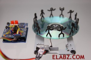
In this final part of the trilogy I am describing the hardware part of the stroboscope project and the making of the zoetrope animations themselves, in hopes that my visitors can take this further and come up with their own animations, which I would absolutely love to see. More details below!
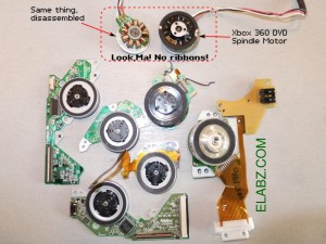
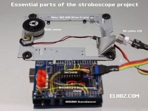
During my search for a perfect donor DVD-RW drive for a (still coming) miniature laser cutter project, I came into possession of some insane amount of broken CD,DVD and Bluray drives and at some point I came across a bunch of broken Xbox 360 drives for sale on eBay that piqued my interest. Once I got them I realized that their main feature is not so much the laser sled positioning mechanism which I was after but rather the three phase BLDC spindle motor that rather basic design which is very compatible with DIY process – no ribbon cables were used. All three windings are conveniently traced to the outside PCB that’s easily solderable. I would have to say that at least one of the Xbox drives I’ve looked into did have a ribbon cable but the ribbon cable ends were not too close together and rather easily solderable themselves. So, if you are interested in this project or just generally in playing with small BLDC motors, definitely do look up broken Xbox drives – they are plentiful and very cheap.The Xbox 360 DVD drive has donated another important part of the project – the frame which holds both the spindle drive and the LED. It already had the mounting holes for the BLDC motor and devising a bracket to hold the LED was just a matter of bending some sheet aluminum left over from another DVD drive teardown.
I opted to have the business end of the stroboscope – the motor and the LED – to be detachable from the Arduino “brains” because I wanted to do a lot of testing and playing with other motors using the same electronics. But if you’re making it a stationary device, the connector between the Arduino Development Shield and the motor frame is completely optional. Additionally, I imagine that with a bit of tweaking the Arduino stack can actually be mounted to the underside of the motor frame (which will have to be raised on some sort of standoffs) to make the entire device even smaller.
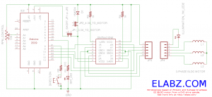
The circuit itself was built on an Arduino Breadboard Development Shield, sans the breadboard. I like the flexibility of the Development Shield even though this circuit could have been implemented using the Motor control shield instead. By the way, I have a feeling that Arduino Breadboard Development Shield no longer refers to a particular PCB because there are at least a couple of different ones out there that I saw. But any kind will do for this project – very limited space is actually needed, just one 16-pin IC, a 5-pin connector, a button and an LED (normally a part of any development shield) and a space for a potentiometer. Please note: even though the photo shows two orange pots on the left of the shield, I ended up using only one to control the rotational speed of the zoetrope animation. The second pot was supposed to control the duration of the flash but I’ve since found that the said duration can only be within a very narrow range (2 to 4ms or 1/500 to 1/250 for you photography enthusiasts out there) and I simply set it with a constant in the code instead. Being able to control the flash duration in real time did not seem to add much to the project.Only a few more components were added to the circuit diagram from the Part 2 of this series of posts, the one that describes the circuit and the software for controlling the BLDC motor. The added parts are the MCU itself (Arduino) and a few controls – the RPM control pot and the direction control button (with the LED to show the direction). The fourth quarter of the QUADRUPLE Half-H Driver SN754410, unused in the previous circuit, is now used to drive the flash LED.
One part of the new scheme that requires some further explanation is the jumpers JP1 and JP2. I have found that the SN754410NE driver gets pretty hot if the stroboscope is left on for a long time. The resistivity of the windings is only 4.3Ω measured across two windings in series (the only way to measure without access to the center point) which means that if we feed the motor control part of SN754410 with the same supply voltage as its logic part +5V, we have more than 1A flowing through it at any given moment, which is higher than what the IC was deigned for. So, I’ve tried two ways of lowering the load supply voltage: lower it some 0.7V by first passing it through the D1 diode (short JP2, open JP1) or take the 3.3V output from Arduino (short JP1, open JP2).
The latter seems to be the best way of controlling overheating. It could have been dropped even more but in the actual DVD I believe the motor is commutated with 1.8V and we don’t have such low source on a *uino. I’ve been too lazy to check for sure but I’ve seen an 1.8V regulator pretty much every time next to the DVD driver IC. Please be warned, however, that the current the motor draws from the Arduino 3.3V regulator seems a bit too much (still pretty high @ 767mA ) and the Arduino’s USB communication stops working. Does not seem to cause any lasting damage but is a major annoyance if you’re trying to load a sketch.
Early in the design process I decided that I will have 12-frame animations. It looked like the figures could be far enough apart and yet enough of them will fit onto a rim of a CD to show a motion complex enough to build this whole project for.
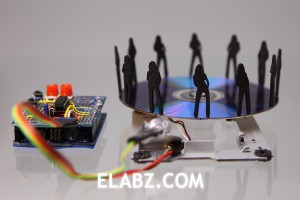
My zoetrope animations (the physical disks with figures) are just throwaway CDs and DVDs with laser-cut foam figures glued at equal intervals 30° apart. The size of the figures was picked specifically to fit a laser cutter made from a DVD. Therefore the length of each piece is limited to only 1.5″. However, I think it’s a perfect size for the diameter of a CD anyway. The source files are included in both SVG and NGC (CNC) format. So, if you don’t have a laser cutter, even a DIY one, you can print the figures out on a card stock paper and cut them out with scissors (this will be tough) or, quite possibly, make use of an electronic cutter machine connected to a PC. I have an older PC paper cutter called SILHOUETTE – maybe I’ll dust it off one day and give it a try.
The first animation is called Rumba because I created it by cutting 12 frames, spaced equally apart, from a video of a Rumba dancer. Then I separated the actual figure from the background, vectorized it with Inkscape, resized to fit the tiny laser cutter and converted into the CNC code using the Inkscape Laserengraver extension. It is quite a bit of work – the disk you see on the picture is probably solid 4-5 hours worth of work, especially if you do it for the first time. Additionally, I didn’t do much choreography research before embarking on this “Rumba” sub-project. If I did, I would have found that Rumba is actually an 8-step dance which is a bit awkward to reproduce with 12 frames. 8 of those are important body positions but I needed to add 4 more and they all have to be equally spaced apart in time, which is almost impossible. In other words with an 8-step dance, 8 frames (or 16 if you feel ambitious) are rather naturally spaces equally apart but 12 frames are not. Instead of going 1-1-1-1… they go 1-1.5-1-1.5… and so what I have in the end is not much of Rumba anymore (which explains why you actually hear Samba in the background on the video at the top of the page 🙂 …
Anyhow, sorry for the digression, not being a dancer myself I never had to think about these things and this project made me to, which was an unexpected bit of fun in and of itself.
For the second animation I picked a much safer subject – stick figures! The figure itself is a result of my fiddling with Stykz – a fine piece of freeware dedicated to creating and animating stick figures. Stykz Linux, according to their site exists but hasn’t been generally released yet. But I was able to run it on Wine just fine.
Had I known more about choreography or dance, I’m sure I could do much better by Stykz and so my hopes are that my readers will be able to use the software to its full potential and amaze my with the results by sending me some photos of their own animations.
Once you’ve cut the figures from your medium of choice, be sure to keep them in the exact order before gluing them to the CD and, preferably, glue them on right away. The order is extremely important and many figures will look very much alike except for some fine details you may not immediately recognize, but if the animation is out of sequence, you’ll be unpleasantly surprised…
I made a little template in the form of a 120mm disk (diameter of a CD) with 12 sectors which you can use to mark the CD before placing the figures. It’s included in the Zip file with the animations.
Loctite Gel Control Super Glue works best for gluing the figures in place. It grabs each piece with enough force and dries fast enough for you to move onto another piece as soon as you positioned the one before it.
The SVG and NGC files with animations and the disk template are here: Zoetrope animations and templates for the Arduino Stroboscope project
The Arduino sketch for the stroboscope is the PWM version from the previous post, I’ll link to it here as well: Arduino Sketch for controlling 3-phase brushless DC (BLDC) motor please note that 12-frame animations are hard-coded into the sketch. In other words, the software does not make calculations for the required flash delay based on a number of frames different than 12. It is entirely possible, especially if the number of frames you’re interested in is divisible by 3, but the code will need to be adjusted.
So, this is it. I hope the three part series has been informative. It has certainly been fun for me. I’ve learned a lot about brushless DC motors and, while working on this particular project, quite a few other ideas were planted in my head and I will most likely be working more with BLDC motors.

Really nice study, I’ve learned a lot.
I’ve some bad news for you, tough: that music on the first video is not a Samba. It’s more like Bossa Nova.
Congrats n thanks for the lesson.
Thanks, Italo! Wow, I wish I was able to pick up such nuances in Latin music which I love to hear but know very little about. I was just going by the title of the song I used: the piece was called “Modern Jazz Samba” by Kevin MacLeod (incompetech.com)
Thanks again for stopping by the site!
I’m not good at recognizing rythms at all… In fact, I hope I haven’t got this one wrong cause it’d be really embrassing given that I’m brazilian…
What do you say about driving a BLDC motor using that technic of rising the voltage well above the maximun recommend, to overcome faster the initial resistance to current due to the inductance, but cut it before it reachs a danger current level?
Well, every time we are talking about controlling voltages by a microcontrolller like Arduino, especially creating unusual waveforms like what you’re describing, the issue of DAC (Digital-to-Analog Conversion) rears its ugly head 🙂 There is no DAC in Arduino or any other comparable MCU. It also just so happens that DAC chips are perhaps the most expensive category of chips out there which kinda goes to show that this conversion is a rather difficult task.
Anyhow, I would have much preferred to feed these motors with just your typical sine wave, 120° apart on each winding and then just control the frequency of the wave. If only creating and controlling a sine wave with an Arduino was that easy… My hunch is that every time we deviate from the sine form of the voltage function, we are actually lowering the efficiency and torque of the motor. But I also have to admit I am scraping the bottom of my own knowledge pool about three phase motors at this point. I have learned about them back in my college days but it was some 25 years ago so I have to revisit the whole thing as I go along with this project.
Cheers!
Would a RC filter + buffer be enough as a DAC in this case?
It’s possible. But… There’s always a but, ha? The driver IC would have to go because it’s designed for digital input. You would be driving through a transistor and controlling this circuit to achieve proper waveform (and you’re not talking about a “simple” sine wave either) would require more analog design than I can stomach.
Plus of course this would be done three times – once for each winding – and they all have to go in sync, so all three RC circuit would have to be built and calibrated with some seriously small tolerances or else you’ll start losing steps once they deviate far enough.
Let me know if you build it though, I would love to see it!
Cheers!
Oh the BUTs…
You’ve made me curious about this. Thanks!
I’ll blow some dust away and see what I can do.
[…] up with a junk box full of optical-drive leftovers. He put some of that surplus to good use by building this stroboscope. As the media spins, the white LED just out of focus in the foreground strobes to freeze the little […]
[…] Zoetrope Doodle (04-09-2012) to celebrate the birthday of Eadweard MuybridgeStarting the Arduino Stroboscope, one of my recent projects, I had no idea the ancient technique could still have such universal […]
[…] projektu – LINK. Na blogu autora znajdziecie sporo innych ciekawych rozwiązań – […]
[…] For more information and the motor tutorial, visit here. […]
[…] projektu – LINK. Na blogu autora znajdziecie sporo innych ciekawych rozwiązań – polecam. Powiązane […]
As i can see that you only feed the motor with 3-phase sin wave. Is that right?
Is there a way to get the back EMF? I want to control BLDC using FOC (Field orientation control), which using back EMF to determine position of rotor.
Thanks for stopping by! No, since these are BLDC motors, the actual winding voltage is a square wave function, not a sine (though it could work with a sine). The sine wave on the graph here http://elabz.com/bldc-motor-with-arduino-circuit-and-software/ is actually describing the PWM duty cycle as a function of time, not the voltage on the windings. The voltage is always either zero or V(motor) – whatever it happens to be. In this case it was +5V – and these CD-ROM BLDC motors would run all the way down to 2V since the load is so light.
This particular circuit would not let you implement EMF-based position feedback because the windings’ ends are always either sinking (connected to ground) or sourcing (connected to V(motor)) current. To use EMF you would need to have at least one winding to be completely disconnected from the driver at some point in the cycle so you can measure its current created by EMF. It’s impossible to do with these Half-H bridge drivers, you need 6 control inputs from the MCU as well as a specialized driver so-called “HI-LOW driver with ENABLE” IC or a circuit on 6 discrete transistors.
What you see here is what you might call a “Simplified” BLDC driving – only 3 control inputs and if you have to use position/speed control, you’ll need to use Hall-effect sensors. Thankfully, most CD-ROM spindle BLDC motors have 3 of those right under the magnet hood.
Thanks for your tutorial!
Two Questions are left
– circuit diagram: the switch for direction buttonpin=8 ist linked to GND. is this right? should it be 5V?
– SN754410: can I also use the L293 driver?
(my motor is vibrating but not rotating..)
Hello Geord, thank you for stopping by and your comments. The direction button works because the Arduino inputs are pulled up internally but I have to concur – this was not the best way to create the input circuit – the resistor has to go from the input pin to the +5V and the button should have connected the input directly to the ground when pressed. I have to admit: I have completely reworked the circuit since then, just need time to draw it in CAD and post again.
As far as L293 vs. SN754410 – they are functional equivalents, should work just fine. In fact, please check this post at the forums where the poster uses exactly this chip L293 : http://elabz.com/forums/motor-control/help-with-arduino-control-of-an-out-runner-brushless-motor/
In that thread I posted a new version of the software, too, and melonFury reported that if works on the old hardware, so you might want to download it and run instead of the Arduino sketch in this blog post. Here is the direct link to the forum post with the new file: http://elabz.com/forums/motor-control/help-with-arduino-control-of-an-out-runner-brushless-motor/msg195/#msg195
Like I said, please stay tuned, I’ll be posting the new schematics and software in a few days.
Cheers!
Hey there. Great post and thank you for sharing. I’m trying to figure out how to control a brushless motor’s exact position with an arduino. Any thoughts? Thanks 🙂
Well, I did give it some thought and have been meaning to try for some time now.
But, in general, the approach would be similar to what you have in a traditional stepper motor: it responds to your advancing the winding commutation step by rotation on a set angle which depends on the number of cogs and poles in the motor. Normally, you are not stopping your commutation sequence and the rotation is continuous. But if you do stop after you advanced a step, the rotor is in a stable position and won’t move further. Next step would see it move at the set angle again and stop again. The 9 cog/12 pole BLDC motor, such as the CD/DVD spindle motor can have 36 of such steps in one rotation (or 36 SPR if you describe is as a stepper), or 10 degree step. This is not very precise compared to most steppers (most are 200 to 400 SPR) but I’ve worked with micro steppers that had only 18 SPR, so 36 can still be useful.
You can rather easily adapt any of the Arduino code you see on this page and the previous post in the three-post series about BLDCs on this blog by adjusting the part of the code that automatically advances those steps to, say, advance only if a button is pressed.
If you want to advance the idea one step further, you may be able to “squeeze” even more steps from a BLDC driven as a stepper by using PWM control of the change from one step to the next. I am not sure how well it will work though because the only truly stable positions are those standard 36 for the given type of the BLDC motor. Anything in between would not be as reliable in terms of positioning.
And a parting thought: most modern CD/DVD spindle BLDC motors have 3 Hall effect sensors built in. You can use those for feedback on the position of the rotor – may come very handy, especially if you’re trying to work with PWM and the rather unstable intermediate positions.
If you build a project with BLDC as a stepper, I would be very interested in hearing about its results. Please post here or in the forums ( http://elabz.com/forums/post-your-projects/ ) about it! I am hoping to find some time soon to work on something along these lines as well.
Thanks for stopping by my blog!
If you are looking to control disk-drive spindle motors or small sensorless BLDC motors, then you should try the DRV11873 from Texas Instruments.
I ran a few tests using the evaluation module and I was pretty happy with the results and how easy was to use it (e.g. allow you to spin the motor in both directions).
http://youtu.be/BehC_sgthc8
Notice that the DRV11873 is limited to BLDC motors with a common lead and upto 1.5A so if you need more power, then the drv8332 is a better alternative.
I have to use DRV8332 to control my BLDC motor. Can you provide me a link where i can get the link where i can find the details of a working circuit?
Thank you for the tip, Al! I should definitely look into this IC (and perhaps some other dedicated controller chips). Love your app with accelerometer control!
Can I use your code to make a bldc for a quadcopter? and replace the h bridge with one that can withstand the high current.
Thanks for the awesome project! =]
Sure, you can try, but I would not recommend it. For a quadcopter BLDC controller you would definitely want to implement some feedback, so you can control the speed. This controller lacks the inputs for feedback.
Thanks for visiting my blog!
Just found your blog and it like it has lots of great well thought out posts! Can’t wait to read more!
Lately, I’ve been trying to learn about motors, different types and how those types are typically controlled.
Do you have any thoughts (or blog posts) on AC Induction motors or AC Synchronous Motors? I understand that unlike BLDC motors that are driven with direct current (trapezoidal backemf), PMSM motors are driven with alternating current due to the different winding (sinusoidal backemf).
But in a practical sense how does the DTC control differ from the Control done for the BLDC motor from the DVD Drive?
Thank’s a lot for all this amount of work!
I learn a lot with it!
Congratulations from a french fan.
All the best!
Is the SN754410 replaceable with the L293D ?
Yup, Texas Instruments datasheet on SN754410 says: Improved Functional Replacement for the L293 . Watch out for pinout! I don’t have L293 datasheet handy to check.
Hi
Your sin(x) wave is going from zero to PWM-max value – so you are driving maximal possible current. If you scaled amplitude of sin(x) to be a fraction of PWM-max and switched off current for the rest of PWM-period (probably better using drivers with ENABLE-pin), you would drive proportionally less current – p.ex. values for sinus wave ranged from 0..15 out of 0..255 PWM steps will give you 16 times less current (with the drawback of 16 times coarser resolution of sinus approximation). The lower the current the lower the torque, but in your case required torque is essentially zero I think.