Pimp Your Chocolates with Arduino IDE and ATTiny13
Way too late for the Valentine’s Day yet maybe just in time for the Mother’s Day this year, I’d like to introduce an electronics project that came about as a result of my reluctance to throw away a nice looking empty box. This year Valentine’s Day came around just about the time I was playing with ATTiny13 micros – I was setting my Arduino IDE up to be able to write code for and burn the program into smaller 8-bit AVR MCUs like ATTiny13. Once the box of chocolates has been freed of its original content by my dear wife Tanya, on the way to the trash I turned it over and realised that there’s a lot of space available inside the plastic insert. I could easily tuck a battery, an MCU and a bunch of LEDs in there for a nice blinking light effect.
{adinserter Internal_left}By counting the possible spots for LED locations in the box, I decided I should use 10 LEDs. In the course of construction it turned out that a couple more could be mounted but 10 LEDs was the starting point for this project. ATTiny13 has only 5 I/Os (if we leave the 6th as RESET so we can more conveniently program it) and so Charlieplexing was used for connecting the LEDs. Charlieplexing is a technique that uses the fact that LEDs are, indeed, diodes and only light up when the current is flowing in one direction. In addition, it is making use of the fact that MCU I/O pins can be switched into a high-Z state (no current flowing in either direction). So, by manipulating the voltage of the outputs and enabling or disabling them when heeded, we can control up to 12 LEDs using only 4 I/O pins. Pretty clever and crafty technique names after Charlie Allen of Maxim Integrated Products who has proposed it first.
I have experimented quite a bit with the actual blinking pattern before settling on the current one that resembles heart bits – two short blinks, then a longer pause. The brightness of the LEDs is controlled with a technique I’d call pseudo-PWM for the duration of one cycle is controlled only by the time it takes the MCU to run through 256 iterations of the code rather than an output of an actual timer. Nevertheless, the end result is rather similar to your normal AnalogWrite() functions in Arduino C: you can make the LED blink “softer” by not only turning it ON and OFF but also raising or lowering its brightness.
Look for the line that starts with byte waveform[16] – these PWM values are what describes the light pattern of each LED. I started with a sine wave waveform (which looked a bit boring) and then added an OFF period that made it look like the heart bit pattern I was looking for.
The bitmap[] and outModes[] arrays are controlling the Charlieplexing pattern – I would not recommend touching those. But you can play with waveform[] as you like if you want to adjust the pattern to your needs.
Download the Charlieplexing_Tiny13_softPWM.ino Sketch 
/*
  Program code for the Pimp Your Chocolates project.
  Charlieplexing 10 LEDs mounted into a chocolate box using ATtiny13 with some brightness control using pseudo-PWM

  The tilt switch motion sensor is connected to Pin 3 (PB4)
  See http://elabz.com/pimp-your-chocolates-with-arduino-ide-and-attiny13/
  for the complete circuit schematics

  Code by Elabz.com
  http://elabz.com/
  This example code is in the public domain. If you end up using it in a project, please drop me a message, I'd be happy to
  know it was of some use. I'll also be happy to feature your project on my site, so send some pictures, too.

  LED hookup can be gleaned from the bitmap[] array values. For example, first LED's value is B00000001 which means that
  to light the LED the D0 has to ho HIGH and D1 - LOW, so the LED's anode is facing D0. LED #2 is between the same legs but in reverse.
  LED #3 is between D0 and D2, LED #4 is the same legs but in reverse and so on.

//       ATMEL ATTINY13 / ARDUINO
//
//                 +-\/-+
// ADC0 (D 5) PB5 1|    |8 Vcc
// ADC3 (D 3) PB3 2|    |7 PB2 (D 2) ADC1
// ADC2 (D 4) PB4 3|    |6 PB1 (D 1) PWM1
//            GND 4|    |5 PB0 (D 0) PWM0
//                 +----+


 */
#include <avr/pgmspace.h>

#include <avr/sleep.h> // sleep code by insidegadgets.com
#ifndef cbi
#define cbi(sfr, bit) (_SFR_BYTE(sfr) &= ~_BV(bit))
#endif
#ifndef sbi
#define sbi(sfr, bit) (_SFR_BYTE(sfr) |= _BV(bit))
#endif


byte bitmap[] PROGMEM ={0B00000001,0B00000010,0B00000001,0B00000100,0B00000001,0B00001000,0B00000010,0B00000100,0B00000010,0B00001000};
byte outModes[] PROGMEM ={0B00000011,0B00000011,0B00000101,0B00000101,0B00001001,0B00001001,0B00000110,0B00000110,0B00001010,0B00001010};
byte waveform[16] PROGMEM = {
  1,5,10,15,78,127,176,217,255,255,255,217,127,37,1,1  // arbitrary waveform (heartbit)
};

boolean d=true; // direction forward=true
byte j=0; // just a counter
unsigned long periodPWM;
int cycleDelay=450;

void setup() {
periodPWM = cycleDelay/16;
  sbi(GIMSK,PCIE); // Turn on Pin Change interrupt
  sbi(PCMSK,PCINT4); // Which pins are affected by the interrupt
}

void loop() {
unsigned  long periodNow;
unsigned long offDelay;
DDRB = 0B00000000; // turn everything off at the beginnig of each LED's cycle - adjust that per your application!
  for(byte x=0; x<16; x++){ // counter for the waveform
      offDelay = 255 - pgm_read_byte(&(waveform[x]));
      periodNow = millis();

      while(millis()-periodNow < periodPWM)
      {
      DDRB = 0B00000000; // turn everything off
      delayMicroseconds(offDelay); // wait for the off period
      PORTB = pgm_read_byte(&(bitmap[j])); // turn LED on
      DDRB = pgm_read_byte(&(outModes[j]));
      delayMicroseconds(pgm_read_byte(&(waveform[x])));   // then wait

   }
  }


  if(j>8)
  { d=false;
  }else if(j<1)
  { d=true;
    DDRB = 0B00000000; // turn everything off at the end of each LED's cycle - adjust that per your application!
    system_sleep();
  }
  if(d){j++;}else{j--;}


}

// From http://interface.khm.de/index.php/lab/experiments/sleep_watchdog_battery/
void system_sleep() {
  cbi(ADCSRA,ADEN); // Switch Analog to Digital converter OFF
  set_sleep_mode(SLEEP_MODE_PWR_DOWN); // Set sleep mode
  sleep_mode(); // System sleeps here
  sbi(ADCSRA,ADEN);  // Switch Analog to Digital converter ON
}

ISR(PCINT0_vect) {

}
Now would be the time to burn the program into the ATTiny13. In order to keep this post to a manageable size, I would like to refer you to an earlier post – How to use ATTiny13 with Arduino IDE which describes setting up Arduino IDE to compile code for and burn it into the smaller AVR chips, including the ATTiny13.
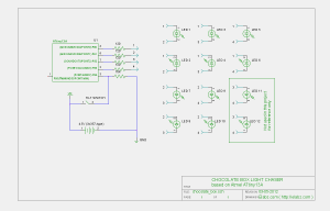
Because of the number of wires involved, its is much easier to show the schematics (on the left) than to explain how it works in words. Just watch for the numbered pins and corresponding LED connections as well as the LED polarity.I decided to forgo a PCB for this project because the space is so tight. But I didn’t want to lose the possibility of removing the ATTiny13 from its socket for re-programming. So, building the entire circuit around an IC socket sounded like a sensible thing to do.
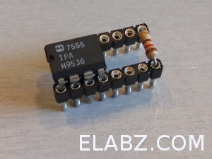
I played around with various types of IC sockets I had and the ones that worked best were the machined ones with round pins of which I only had single row type. That’s why the picture on the left looks so strange. The 555 timer that’s plugged into the socket is there simply to hold the two single-row 8-pin sockets together at the right distance.
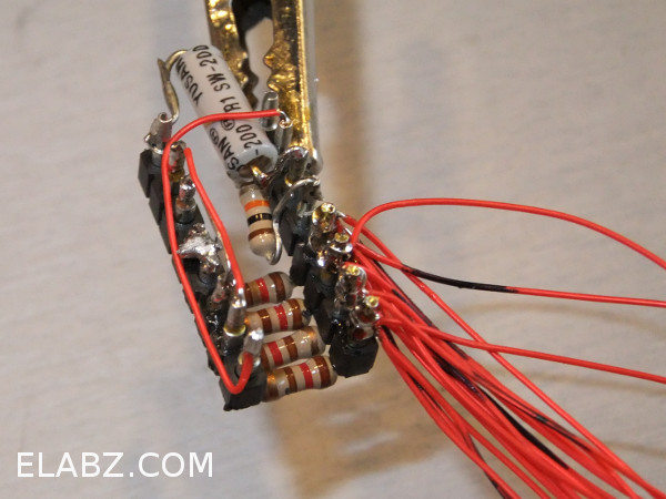
The four resistors needed for the LEDs were then bent to size, inserted into the socket’s remaining pins and soldered in place. After the 120 Ohm resistors have been soldered in place, the socket is pretty solid and the place holder 8-pin IC can be removed. If you turn the socket around, you can solder the ball tilt switch (motion sensor) and its 10K resistor. Then solder in place the connections of the 120 Ohm resistors to the I/O pins of the MCU.
Next prep the LEDs with 10-12″ (25 – 30cm) long 30AWG wires. You can use thicker wires of course but you don’t want them to be too springy – the inside plastic insert of the box is rather flimsy and you don’t want the wires to push it too much. The leads of the LEDs should be shortened. It would also make sense to mark the wires with a Sharpie now because polarity is very important for chrlieplexed LEDs.
Once the LEDs are prepped with wires (use red whenever possible – it will be well hidden behind the red plastic insert), you can start soldering them to the socket. All the soldering points are on the same side of the sockets. It’s best if you start with LED #1 and go sequentially because there’s a certain pattern to the combination of pin # and polarity. if you follow the pattern, your chances of mis-wiring an LED are smaller. In fact, I think only 9 LEDs are working on the video. They still look OK and I did not have a heart to go troubleshooting the wiring.
Don’t use too much solder, at least not for the first LEDs because the first two pins should receive 6 wires and you’re adding a little solder with each of them.
With all LED wires soldered, it’s time to solder the battery box and give it a test. Just don’t forget to insert the actual programmed ATTiny13 first!
I am using three 357-type batteries in a heat-shrinked improvised battery pack here on the photos but I have later replaced the one-time use device with a battery box shown on the video. The latter came from a powered squeaking pet toy which my dog has very timely destroyed just in time for me to make the change before shooting the video. I would have to say that the ability to change batteries is very convenient! I gave my dog an extra treat for that 🙂
Note that an optional power switch was used between the battery and the circuit. This was more for the benefit of my taking pictures of the device than for its operation. The MCU is going to sleep once there’s been no movement for a certain period of time and the power consumption is very low. It ran for about a month on that battery pack.
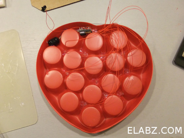
Once you’ve verified operation of the complete circuit, use hot glue gun to mount all the components and the LEDs into the nukes and crannies of the red plastic insert. It has just the right size valleys all the way around the rim for the larger components – the battery pack and the MCU. When you glue the LEDs, you would need to randomize their locations. It was too much for the little MCU to implement flashing a random LED in the software (the random() function takes too much memory) and so you would want to spread the LEDs randomly around the insert for a more attractive blinking pattern. I found that the randomizing case naturally to me simply because I failed to number to LEDs. So, by the time I was gluing them in place, I already forgot which is which, and that worked out just fine as a substitute for the memory-hungry random() 🙂
Once the glue is set, put the insert back into the box, fill it with chocolates and set it on a table for someone to discover them, touch and be amused by the unexpected light show!


Looks cool!
Thanks, smeezekitty. I appreciate your support, too. I came across your ATtiny13 library while gathering info for this particular project. So, you’ve helped, too.
In retrospect: I wish I investigated the possibility of dropping the clock even lower, as close to the 128KHz in your examples as possible (continuing on our discussion at arduino.cc forums). I was hoping that the power consumption would be less. It worked for about a month on a pack of three LR44 (in other words it started at 4.5V and probably worked down to 3.6 – 3.5V or just about). I was kinda hoping that I would see the MCU continuing to work all the way down to 3V which would make the LEDs visibly dimmer yet still blinking. That didn’t happen because at 4.8MHz it can’t start at such low voltage.
Maybe one of those days I’ll redo the design and take this into account. I’ve seen Ferrero Rocher selling their chocolates in a transparent container in the form of an egg around the Easter time. There’s A TON of space inside, it’s just begging to be converted into a blinking surprise Easter egg 🙂 . I think my next step will be to figure out what would be the lowest frequency which still allows for the pseudo-PWM based on miscros().
Thanks for stopping by!
I am surprised it did not work any lower. Even a full Arduino will work down to 3v at 16Mhz. Atleast with the 128Khz clock, the voltage goes below the LED forward voltage before the MCU stops (~1.6v).
I think there’s another issue here that could have contributed to shorter battery life: when I burned the configuration fuses for the ATtiny13, I set the brown-out detection (BOD). BOD does contribute to power consumption and the datasheet refers to its consumption in the sleep modes as “significant”. I guess I didn’t quite appreciate how significant that was. Also, it’s quite possible that I’ve set it at a way too high a value – the 00 BOD configuration bits actually mean 4.1V (reading the datasheet just now). I have to verify how I burned fuses for this particular chip but I’m afraid 00 is exactly what it was
BOD would not let the MCU start below a certain voltage level by constantly resetting it. I guess I should investigate what exactly has happened when the light went off after the month of normal operation. It’s quite possible that the MCU was still trying to run but BOD kept resetting it the instant the first LED would be turned on, which would drop the voltage below the Vbod level.
I’ll do some research on that when I get time – I’m very interested in the issue of micropower and feel like I’ve a lot to learn on how to properly set MCUs up for longer battery operation.
Cheers!
Wow, you made hack a day!
Hi,
I just tried to set things up like you did. But uploading the code to the ATTiny13 with Arduino fails all the time. I was able to burn the bootloader, getting some erros.
But when ever I try to upload the sketch it gives a lot of errors like “byte has no something” … unfortunately I´m not at the setup tight now …
I’ll be glad to help, Chris. Let’s just take this over to the forums, Help section : http://elabz.com/forums/help-and-feedback/ It is much easier to post long listings of error messages there and the question-answer threads are much easier to follow. See you there!
ah sorry, did not know there was a forum near by 😉 I´ll post there with more detailed error messages.
[…] in time for Mothers Day. Dress up your box of boring chocolates with some blinking LEDs. This project by Dmitriy Abaimov uses an ATTiny13 programmed using the Arduino IDE to do the […]
[…] mother’s day, why not spice them up a little with some LEDs? [Dmitry] shows how you can easily add some flashing lights to the packaging without really modifying it. He’s using an ATtiny13 which only has 5 I/O pins, so he had to […]
[…] Hacked Chocolate Box has Blinking LEDs controlled by an ATTiny13 via Hacked Gadgets. Way too late for the Valentine’s Day yet maybe just in time for the Mother’s Day this year, I’d like to introduce an electronics project that came about as a result of my reluctance to throw away a nice looking empty box. This year Valentine’s Day came around just about the time I was playing with ATTiny13 micros – I was setting my Arduino IDE up to be able to write code for and burn the program into smaller 8-bit AVR MCUs like ATTiny13. Once the box of chocolates has been freed of its original content by my dear wife Tanya, on the way to the trash I turned it over and realised that there’s a lot of space available inside the plastic insert. I could easily tuck a battery, an MCU and a bunch of LEDs in there for a nice blinking light effect. Filed under: arduino,leds-lcds — by Becky Stern, posted May 11, 2012 at 4:00 pm Comments (0) Try Adafruit's new iPhone & iPad app for makers! Circuit Playground! "Incredibly handy for anyone working in electronics. Perfect for engineers and non-engineers alike." Looking for engineers, makers and the builders of dreams? Try our Adafruit job boards. Join our weekly Adafruit SHOW-AND-TELL at 9:30pm ET every Saturday night! Then at 10pm, ASK-AN-ENGINEER with Ladyada and the Adafruit team! hr{display:none} .in_the_store{background-image: url("https://www.adafruit.com/includes/templates/adafruit/images/side_back.jpg"); background-repeat: repeat-x;width:634px;border: 1px solid #CCCCCC; float:left;} In the Adafruit Store: Passive PoE Injector Cable Set BMP085 Barometric Pressure/Temperature/Altitude Sensor- 5V ready Conway's Game of Life Kit […]
[…] Get making! The code and instructions can be found here. […]
[…] at eLABZ, Dmitriy made an LED-enhanced box of chocolates that would delight any maker’s mom on Mother’s Day. He was able to tuck an ATtiny13 […]
[…] at eLABZ, Dmitriy made an LED-enhanced box of chocolates that would delight any maker’s mom on Mother’s Day. He was able to tuck an ATtiny13 underneath […]
[…] The circuit schematics for this project is very similar to that of the previous two LED blinkers – the only difference of course is the amount of Charlieplexed LEDs – I figured 6 LEDs would have been enough for the simple message I wanted to show. This time I also decided to make a board for the project (see picture below), and BatchPCB is making it as I type this, but I have severely underestimated the time it takes to make and ship a PCB from China around the time of the Chinese Lunar New Year, so to build this project in time for Valentine’s, I had to revert back to the freeform PCB-less builts like the previous LED blinker project here and here […]
[…] over at eLABZ enhanced an off-the-shelf box of chocolates with an array of 10 charlieplexed LEDs mounted underneath the red plastic tray together with an […]
[…] Dmitriy Abaimov shares a project toDress Up Your Standard Chocolate Box with Arduino-Controlled Lights, at eLabz: […]