Laser Diode Driver with TTL Control. PCB V2.0 is ready.
This is another one of my belated updates. It has been about 3 months now since I’ve received the boards for the updated version of the laser diode driver from Olimex. However, I haven’t had a chance to work on any project that required a laser driver until just recently and so the boards were not populated and tested for the longest time. Finally, I can report that the design works, here are some pictures and there’s the Eagle board file for the PCB later in the post.
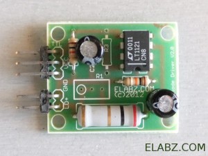
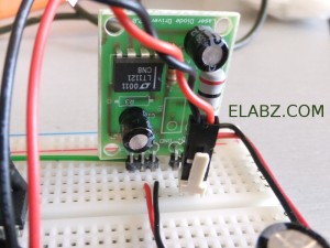
The board was designed with breadboard use in mind and so I spaced the headers for the inputs and the outputs accordingly, see the picture on the left. I don’t know if installing the 90 degree headers to stand the board up was such a good idea, I’ll probably do other boards with simple straight up headers.
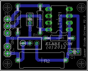
I haven’t installed the potentiometer (R1, space indicated on the board) because the project I’m using it for, the DVD CNC laser cutter, does not really require much current adjustment, which is what R1 is doing. I’m powering all parts of the CNC laser cutter, including the laser diode driver from a +5V power supply and it just happens that the 2 Ohm resistor R2 gives me just the right current, approximately 150mA, needed for the red laser diode I’ve harvested from a DVD burner drive. If you did really need current adjustment, the power supply would have to be raised to about +9V , the R2 would have to be 10 Ohm or just about and the 100 ohm R1 potentiometer would need to be installed.
{adinserter Internal_left}The R3 resistor which pulls the control input of the LT1121 chip to supply voltage has not been installed either. If you need the driver normally ON, install R3 and don’t install R4. If you need it normally OFF, don’t install R3 and install R4, which is what I’ve done here.
It may just be my luck or it may be a temporary situation, but when I started to design this driver back in late 2010, the LT1121 power regulator chip was very common and very cheap, about $0.40 each, delivered from China. It was one of the most important reasons I based the design on LT1121, actually. It took me a while to get a final usable design and have the boards manufactured, so fast forward to July 2012 – the LT1121 chip is nowhere to be found for less than $5 EACH! I still have 3 or 4 of these chips left laying around the bench, and I’m obviously on the lookout for a good source. If anyone knows a good source, I would appreciate a tip!
And last but not least: the Eagle board and schematics files are here:
 Laser Diode Driver V2 Eagle schematics and board files


Hi!
I have a question about the schematic. If I read it correctly LT1121 sets 3.75V on PIN2 which goes across R2 and LD in series. However everything I read strongly suggests that you should never drive a laser diode with voltage. Am i missing something here?
It is true, the voltage regulator will try to raise the voltage on its output until the voltage on the ADJ pin (Pin 2 on LT1121) equals a pre-set value, for LI1121 it’s 3.75V. In this schematic ( http://elabz.com/wp-content/uploads/2012/01/Elabz_TTL_Controlled_Laser_Driver.png ) the output (Pin 1) and ADJ (Pin 2) are shorted and the only path to ground is through the R2 (and, if installed, R1) and the laser diode. The voltage across a red laser diode is always 2.5V and therefore the rest of the 1.25V difference has to come from the current passing through the laser diode and R2. In other words, the regulator does not raise voltage across the laser diode, which would be bad for the diode. It raises the voltage across the R2 resistor until the sum of the voltages on R2 and LD becomes equal 3.75V. If you use higher value R2, the voltage will rise at smaller current and so the current through the LD will be less.
Check out the LTSpice model for the driver here: http://elabz.com/wp-content/uploads/2012/01/current_source.asc You can play around with input voltages to see that the current across the laser diode is constant from about 5V to all the way up to the upper limit of LT1121 – 30V
Thanks for stopping by my blog!
Digi-Key has them for $3/ea, or $2/ea for 25.
If you saw these somewhere for $0.40, they almost certainly weren’t genuine Linear parts — Linear (and Analog Devices, for that matter) don’t make such inexpensive parts… 1/2 🙂
The ones you saw may have been something like the LT1118 that other companies make pin-compatibles of for 10-25% of the original’s cost.
good luck!
-e
$1.83 direct from Linear or $1.50 in quantity of 1K
a little question: I am using Multisim to simulate your circuit and what load should I use?
When I use a resistor as load the current is always around 6mA. Should I change a load and what it should be?
Thanks for stopping by, Tony. I’ve posted an LTSpice model of the driver some time ago, check it out: http://elabz.com/ttl-controlled-laser-diode-driver/ It includes the full model of the laser diode as output (including the brightness feedback photodiode, not used in this driver, just in case you need it in a different driver design). Hope you can use it in Multisim or re-create it in Multisim – it’s a very simple circuit.
So many thanks!
Hi
I just want know did you use the laser diode straight from the DVD player or did you have to put extra stuff on the the laser diode to focus the beam.
Thanks
Hello Carel, yes, you do need housing with lens for the diode in order to focus the beam. Otherwise it goes out at a whopping 30 degree aperture – not very useful for cutting anything with the beam (the original intent of the project). I explain the housing I used in better detail here. Thanks for stopping by my blog!
I have question plz how do i connect capacitor on the pcb and on schematic there is not born positive plz reply
Perhaps it might be a little more clear on the schematic here: http://elabz.com/ttl-controlled-laser-diode-driver/ . But getting back to the PCB picture in this post, the pin on the right (if you are looking at the board from the component side) is connected to the ground, so the pin on the left then is the one that’s usually marked with a little “+” on the electrolytic capacitors. In general, the flat line on the electrolytic capacitor symbol is the positive side and the curved one is the ground.
Why the r2 resistor is very big i can replace it with normal one 1/2 watt or 1/4 watt
It’s true, in many cases the size of the resistor is an overkill. Just pick one that is appropriate for the heat dissipation at the current level you’re looking for: if your resistor is 2 Ohm and you are anticipating 200mA of current through the laser diode, you would have to size R2 for at least 2*0.200=0.4 or approx 1/2 W
I know were you can get about 83 of these for $2.00 EA can you send me a DXF of the foil pattern of your board, I would like to build a couple of these.
Thanks for stopping by, Tom. I don’t have a ready-made DXF but the Eagle board file attached above in this post ( http://elabz.com/wp-content/uploads/2012/07/LaserDiodeDriver.zip ) can be converted with the free version of Eagle.
I have a question on the R3/R4 and ttl. So you say that if R4 is installed its normally off. So the laser is off until an input is detected on the TTL line? Am I correct on this.
That’s right – R4 pulls the Enable input of the chip down, and the driver will be off until something (like a I/O pin of an Arduino for example) brings that input up to TTL high.
Thanks for stopping by!
what you think about MIC5235?
on Chinese drivers usually write TTL – 30/50khz. But there are problems where the need for greater speed. What do you think LT1121 allows you to modulation at a higher frequency? Say 5-20 megahertz? I read the datasheet but could not find this information out there.
I know that there is a chip for fiber lasers. They work at gigahertz frequencies. But there is a very weak power output.
High frequency switching is not going to work with this driver. I tried to pulse the laser at about 20-50ms and the laser just could not reach the full brightness. So, I don’t think you can expect reliable results trying to modulate it even at 30kHz, unfortunately. I ended up driving that laser diode as a simple LED with a switching transistor – worked just fine. The only precaution I used was to limit the current to half of the max with a resistor – even half current modulated at > 50kHz produces much brighter output (or any output at all) than a laser driver based on LT1121.
I mostly use this particular driver in laser cutting CNC setup where the modulation frequency rarely, if ever, goes above 100Hz. Only On/Off, no PWM.
Don’t know much about any particular fiber optics driver but those more readily available and more compatible with this type of laser diode are from multimode-based equipment and so they don’t really need to work at GHz frequencies. I believe something like 60MHz or less with encoding will get you to 100Mb/s that you need for 100Base-FX Ethernet. I have to brush up on modern network speed standards but I don’t believe there’s anything on multimode fiber yet (or will ever be) that pushes more than 1Gb/s through an individual fiber, so your pulse frequencies are always going to be well below 1GHz. But 5-20 MHz should work.
Cheers!
Hello
First off, let me say that I like your design with LT1121, as compared to the other LM317 designs, mostly because I also want to use my laser on a machine.
So thank you for sharing your knowledge and posting the design.
However, I must admit than I am more into the mechanical aspect of stuff, as compared to the electronic aspect, so I could use a little more help, if you would be so kind.
I would like to build this circuit, just as you intended to build it. EAGLE makes it very hard for the average user to discern various attributes of some of the components utilized. So could you please…..
1. Provide a part number for the R1 trimmer, which would match the characteristics of the circuit as you designed it. For example, one that would match the pin hole locations and wattage.
2. Provide the various wattage values for R2, R3, R4, and R5, as you intended for this design.
3. Provide the voltage values for C1 and C2, as you intended for this design.
I am assuming that you chose your components according to the maximum VCC of 30V, but I could be wrong.
Anytime or effort that you may put forth into fulfilling this request, will be greatly appreciated.
Thanks in advance….
Bruce
Thanks for stopping by, Bruce. It has been awhile since I have updated or frankly, even looked at the circuit, so I will try to provide some info from memory. Can’t say anything about the P/N of the potentiometer as well as other components – may were chosen simply because I had some in the loose parts bin. Basically, it should be one able to dissipate the amount of heat it will produce at something like 1/10th of the current through the diode. My guess would be 0.25W – 1W if you can find it. In my case I used something much weaker than that but I cannot exactly say this trimmer is even all that useful – pretty much in all the instances where I used this driver, I used it on max current, so it was simply only R2 without R1 installed.
R2 should be rather high wattage – say, 2W (again – R * V will get you the approx value), the rest are – anything you find laying around the shop. 1/8 W should suffice.
As far as caps – I used 16V only because I ended up never using a supply higher than 12V. If you want to increase the supply voltage, use higher voltage rated caps.
Sorry I cannot be more helpful – this is a rather old project of mine that I don’t even remember much about at this point.
Good luck!
Thanks for taking the time to answer. I truly appreciate it.
Is this the one you’re wanting to source?
https://www.aliexpress.com/item/4000117844997.html
U$0.26 each plus shipping in five packs