Laser Diode Driver Based on LT1121 Voltage Regulator – schematic and PCB

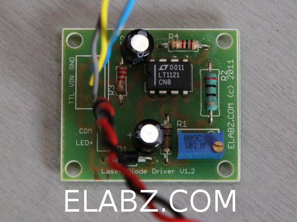
Laser diode driver based on LT1121. PCB version 1.2, populated.
This post is kept alive just to hold the old comments – please see the corrected circuit design here: http://elabz.com/ttl-controlled-laser-diode-driver/
Update
I’m having some issues with overheating of both the LT1121 IC and the R1 potentiometer, so I advise you to approach this design with caution. I will be revising it in near future. I would love to hear any suggestions for improving this design from the site visitors!
{adinserter Internal_left}I’ve been using an off-the-shelf laser diode driver for my CNC laser cutting projects and came to realize that I need a different driver. Maybe not so small as to fit inside the laser diode enclosure but capable of driving both red diodes in 100mA-200mA range and blue diodes in 75mA-130mA. In fact, having the driver inside the laser diode housing proved to be inconvenient for this application because it is hard to monitor the current and also both the driver and the diode emit considerable amount of heat and I see no good reason to put them together to double that heat up inside a small enclosed space.
Pretty much all the DIY laser diode driver circuits floating around the Internet, such as rog8811 I’ve looked at initially, are based on the venerable LM317 adjustable voltage regulator that’s being “duped” into constant current mode by creating a feedback loop through a series of resistors (one pot and one constant) between the output and the “adjust” input. However, these LM317-based circuits are pretty much all designed for various laser pointers and therefore lack the capacity to be ON/OFF controlled via a TTL-level signal – an important feature for a CNC laser cutter.

ELABZ.COM Laser Diode Driver with TTL Shutdown. Schematic.
The LM317 is very old and I thought there must be a better way to build such driver circuit using the same feedback technique but a modern regulator IC with the shutdown feature that I need for CNC. So I’ve found a bunch of LT1121 adjustable voltage regulator ICs on the bottom of my analog IC parts bin and, after reading the datasheet, it turned out that it’s a perfect IC to build a constant current laser diode driver on. It is a low dropout regulator, has a shutdown TTL-level input and is capable of supplying 150mA current but in my tests I was running is just fine at 200+mA and it did not generate any heat whatsoever.
Despite having more features, LT1121 isn’t more expensive than LM317 and can be easily sourced anywhere, including eBay. It has one limitation that needs to be taken into account when using the driver circuit: the internal voltage reference is 3.75V as opposed to 1.25V for LM317 and therefore it has to be supplied with 2.5V higher voltage than a similar LM317-based laser driver circuit. Basically, for a red laser diode the supply voltage has to be 7V or higher and for a blue laser diode the supply has to be 9V+ . When using an Arduino-based controller, it’s best to supply this driver from the VIN pin (AKA “raw 9V”) rather than the regulated 5V rail.

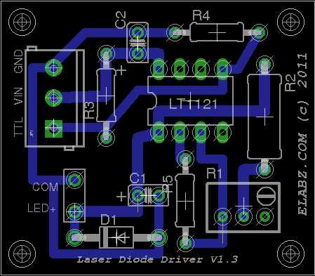
Elabz.com Laser Diode Driver based on LT1121. Board.
Here is a board layout that has been slightly adjusted after I’ve populated the first PCBs ordered from Olimex. That’s why the version on the board layout (1.3) and on the photos (1.2) are different. Basically, I just moved the LT1121 chip a bit down to make more room for the capacitor. Note that LT1121 produces stable output with capacitors as low as 0.33uF, so small ceramic ones can be used instead.

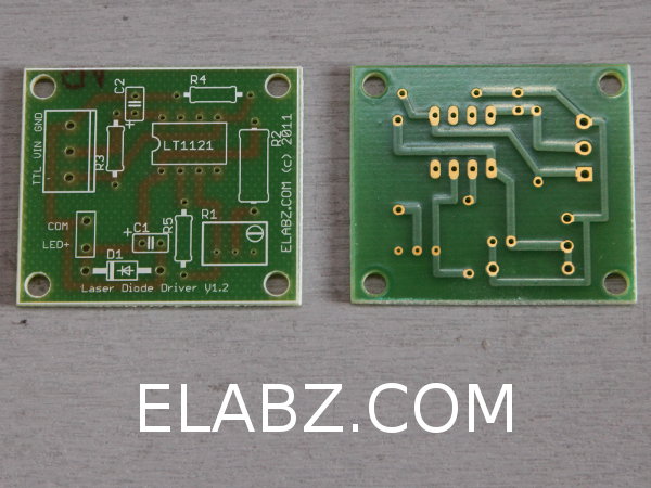
ELABZ.COM Laser Diode Driver PCB V.1.2 back and front
The circuit was designed in Eagle and here are the Eagle schematic and board files.
Elabz.com Laser Diode Driver Eagle files
License

where can i purchase this board to build do you sell them , or can the whole board be purchased complete ready to use
thanks for your time
ghostlx
Thank you for stopping by, Mr. Ghost!
It’s an interesting question. I did not have plans for making this board available commercially (at least not this particular early version) but I had to purchase 12 of these to fill a whole panel and I only need 3 or 4 for myself. So, I would not mind selling you either the board or I can populate it for you if you like for some extra charge.
The bare board would cost $4.00 + shipping and a populated/tested one $12.00 + shipping
If that sounds like a fair deal, please respond here (or contact me directly at http://elabz.com/contact/ ) and I’ll send you a PayPal invoice for the purchase.
Thanks!
can someone send me a link to the sites where i can buy those ic and the rest
thanks for circuit diagram.
from Bangladesh
Still have some boards floating around?
Got boards but not confidence in them 🙁
Populated a couple some time ago and burned a few laser diodes right off the bat. LT1121 does not seem to like its ground suspended and I haven’t found the way to connect it to the actual ground yet have current sensing feedback fed to the control pin. Looking at it again now, it appears I’ve got pins 2 and 3 switched on the schematic and therefore on the board. Otherwise can’t really explain how it was working when breadboarded … One of those head scratchers.
If after this dangerously sounding warning you still want it, let me know. I’ll email you address to send a self-stamped envelope to and I’ll just mail you one unpopulated board for free.
Thanks for stopping by my blog,
Cheers!
[…] to build one based on Linear Technology’s LT1121 voltage regulator with Enable input but the driver design that came out was not exactly successful So, I took another stub at it […]
Hello there,
I am a student from China.
About the overheating problem, I would like to introduce this: http://en.wikipedia.org/wiki/Switched-mode_power_supply
My teacher said this will reduce a lot heat.
Hope this will help.
Thank you for the tip, Tony. Well, there were couple of issues with this design, not the least of which was that it was not actually working 🙁 But I have since re-done the driver put the new working laser diode circuit and board here. The problem with the heat in the initial design was not so much the inefficiency of voltage conversion (LT1121 are actually low voltage dropout regulators, so they are rather efficient) but the simple fact that the current sensing resistor was in the same leg of the circuit as the laser diode and just needed to be rated for higher current than I anticipated. So, anyway, if you are looking for a laser diode driver circuit, be sure NOT to use the one on this page and go right to the corrected version instead.
Thanks for stopping by!
sorry, I guess it should be this site:
http://en.wikipedia.org/wiki/DC-to-DC_converter#Switched-mode_conversion
Hello sir,
I working on project titled LASER ENGRAVING MACHINE.
I want to ask that whether this circuit is more appropriate or the circuit that i took from this website http://funofdiy.blogspot.co.uk/2013/10/a-raspberry-pi-controlled-mini-laser.html which is using LM317t in this circuit.
I took laser diode from DVD RW.
second question is that laser is not of high power it is due to the lens that i havent used yet or their is some other problem.
Hello Gul, thank you for stopping by. It is hard to say if this circuit is more appropriate or not. I came up with it because I wanted to use the TTL-control capabilities of the LT1121 regulators I had on hand (LM317 requires external circuitry for that). Since then, I would say that availability of the LT1121 is not very good, and if you can find it, it’s usually too expensive (to my liking, anyway). From the standpoint of using the LT1121 as a current regulator instead of voltage regulator, which is what it was designed for, there is also one additional limitation there – the low voltage on the regulating pin. That limits the amount of current you can measure/control. I was able to bring the current up to about 250mA, but to go any higher than that with a red laser diode seems impractical (because you need resistors with high accuracy values of fractional Ohms).
Also, LM317 – based schemes are more common, and you will be able to find more information on those.
One last comment- if you are planning to go higher than 200-250mA, you are going to need a high power laser diode. DVD-RW drives only go as high as 250mA to the best of my knowledge. You may have to switch to blue high power (~1W) laser diodes used in projectors, which usually means that you have to buy the diode as a separate unit. They used to be expensive, not sure what they cost now.
Good luck!
Hey!
so does this easily work with arduino? have you tested it?
thanks!
aim 60 years old retired man experiment of laser diode 808nm,910nm for dental use your help required for driver board with fiber optic
Regard
zafar