Manually controlling bipolar stepper motor with Arduino and EasyDriver
Stepper motors are great for accurate positioning because they move in discrete steps – a feature that makes them very appropriate for CNC software control. But every once in a while you have an application where you need to press a button and rotate some kind of a jig at a preset angle or move something a preset distance if it’s a stepper-driven linear stage. So, I decided to modify an earlier Arduino sketch I wrote for testing the world’s smallest stepper motor to make it a bit more useful (and clean any bugs in the process). Keep reading to see what came out …
Shout outs to forum user Yellow who in this thread provided an inspiration for the code modification. I had another project in mind but was dragging my foot for a long time, and seeing that someone else can also use results of your work provides a great motivation, so thanks, Yellow!
{adinserter Internal_left}
 Arduino sketch for the manual EasyDriver control of bipolar stepper motors
Also see the code in the post below. The circuit is extremely simple because most of the hard work of commutating the windings of the stepper is done by the Allegro A3967 motor controller chip, mounted on the EasyDriver board. The Arduino can be any incarnation thereof. I used Nano and I had to move the outputs away from the D0 and D1 because it was messing with uploads (I think it’s only a problem with Nano specifically) but any Arduino will do – there are only 8 digital I/Os and one analog.
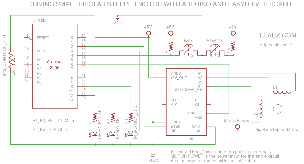
Circuit diagram for the EasyDriver + Arduino manual stepper control
The parts list for the project is very short:
-
- Arduino. Any type will be adequate.
- EasyDriver board, populated. Please check with the author, Brian Schmalz on the best source of them.
- Bipolar stepper motor i.e. one with 4 leads. 6- and 8-lead unipolar stepper can also be converted to bipolar by connecting the proper ends of the windings together and floating the center point – not a very difficult task but outside of the scope of this post
- 2 x pushbuttons for LEFT/RIGH a.k.a. UP/DOWN a.k.a CW/CCW control
- 3 x LED for indicators, preferably different color
- 3 x 510 Ohm current limiting resistors for the LEDs
- 2 x 10K Ohm pullup resistors for the buttons
- 1 x 10K Ohm potentiometer (anything between 1K and 100K is fine)
Couple of lines in the Arduino code you may want to look at and adjust to your needs are highlighted in the code below.
Note the int stepsPassedMax = 160; line (line 28).Here 160 means 20 full steps in 1/8th microstepping mode. It just happens that the micro stepper I was using earlier (not the one on the video) had 20 SPR (Steps Per Revolution) and this would have been one 360 degree rotation of the motor’s shaft. If you have a better stepper (200SPR is common), it may only be 1/10th of one rotation – check with the datahseet on the motor and adjust the stepsPassedMax accordingly or send, say, 200*8= 1600 steps and see if the motor completes a full 360 degree revolution if you don’t have a datasheet and suspect that this is a 200SPR motor.
Another adjustment you may make is the desired RPMs or, more appropriately, angular speed since you may not even need a full rotation, hence no R in RPM:
The smaller the stepDelay variable, the faster the motor turns. See lines 36 and 60 in the code below.
Below is the complete code:
/* EasyDriver stepper test sketch Circuit diagram and description at http://elabz.com/manually-controlling-bipolar-stepper-motor-with-arduino-and-esaydriver/ */ // constants won't change. They're used here to // set pin numbers: const byte stepUpPin = 4; // the number of the step pin const byte stepDownPin = 5; // the number of the step pin const byte stepOut = 2; const byte directionOut = 3; const byte ledPin = 12; // pin # for direction indicator LED const byte readyPin = 11; //pin # for LED that comes on when all the steps have been completed const byte inMotionPin = 10; // pin # for the LED that light up when the stepper is supposed to be still moving const byte ratePin = 0; // A0 - analog 0 pin on Arduino to control the stepping dealy (i.e. RPMs) const byte enablePin = 6; // turn EasyDriver off when not turning (saves power but ONLY use when there's no need to hold position) // Variables will change: byte ledState = LOW; // the current state of the output pin byte lastStepUpButtonState = HIGH; // the previous reading from the step UP pin byte lastStepDownButtonState = HIGH; // the previous reading from the step DOWN pin byte directionState=HIGH; // the current direction byte stepUpState=HIGH; // the current state of UP button byte stepDownState=HIGH; // the current state of DOWN button int stepsPassed = 0; //how many steps? int stepsPassedMax = 160; // trying to calculate steps per revolution (remember the microstepping settings 1/8th is default) // most small and micro steppers, especially those that came from a CD- or DVD-R/RW drives // have 20 steps per revolution. So 160 mircosteps should make the motor spin 360 degrees once. long lastStepUpDebounceTime = 0; // the last time the output pin was toggled long lastStepDownDebounceTime = 0; // the last time the output pin was toggled long debounceDelay = 50; // the debounce time in ms; increase if the output flickers long stepDelayBase = 1; // 1ms base rate. Multiply by the reading from the RATE potentiometer for actual step delay long stepDelay; // long lastStepTime = 0; // last time the step signal was sent void setup() { pinMode(stepUpPin, INPUT); pinMode(stepDownPin, INPUT); pinMode(ratePin, INPUT); pinMode(stepOut, OUTPUT); pinMode(directionOut, OUTPUT); pinMode(ledPin, OUTPUT); pinMode(readyPin, OUTPUT); pinMode(inMotionPin, OUTPUT); pinMode(enablePin, OUTPUT); digitalWrite(readyPin, HIGH); // turn OFF all LEDs in the beginning digitalWrite(inMotionPin, HIGH); // turn OFF all LEDs in the beginning digitalWrite(ledPin, HIGH); // turn OFF all LEDs in the beginning } void loop() { // read the state of the switch into a local variable: int readingStepUp = digitalRead(stepUpPin); int readingStepDown = digitalRead(stepDownPin); stepDelay = analogRead(ratePin) * stepDelayBase/50; if(stepDelay < 1) stepDelay = 1; // reality check - a pot can read 0 and then it would mean infinite RMP - not possible if(readingStepUp == LOW || readingStepDown == LOW) { // only read buttons if either one of them is LOW // If the switch changed, due to noise or pressing: if (readingStepUp != lastStepUpButtonState) { // reset the debouncing timer lastStepUpDebounceTime = millis(); lastStepUpButtonState = readingStepUp; } if ((millis() - lastStepUpDebounceTime) > debounceDelay) { // whatever the reading is at, it's been there for longer // than the debounce delay, so take it as the actual current state: lastStepUpButtonState = readingStepUp; lastStepUpDebounceTime = millis(); stepUpState = readingStepUp; } // If the switch changed, due to noise or pressing: if (readingStepDown != lastStepDownButtonState) { // reset the debouncing timer lastStepDownDebounceTime = millis(); lastStepDownButtonState = readingStepDown; } if ((millis() - lastStepDownDebounceTime) > debounceDelay) { // whatever the reading is at, it's been there for longer // than the debounce delay, so take it as the actual current state: lastStepDownButtonState = readingStepDown; lastStepDownDebounceTime = millis(); stepDownState = readingStepDown; } }else{ stepUpState = HIGH; stepDownState = HIGH; } // end of if block that reads button states if(stepsPassed == 0 ) { // if the previous command has completed, make the direction decision if(stepUpState == LOW || stepDownState == LOW) { if(stepUpState == LOW && stepDownState == LOW) { directionState = LOW; } // why are you holding both UP and DOWN buttons? if(stepUpState == LOW && stepDownState == HIGH) { directionState = HIGH;} // go up if(stepUpState == HIGH && stepDownState == LOW) { directionState = LOW;} // go down stepsPassed = stepsPassedMax+1; } } if(stepsPassed > 0 ) // send step signals now { digitalWrite(enablePin, LOW); // wake up digitalWrite(ledPin, directionState); // set proper direction digitalWrite(directionOut, directionState); if((millis() - lastStepTime) > stepDelay) // delay expired, send another step { digitalWrite(stepOut, HIGH); stepsPassed--; lastStepTime = millis(); }else { // time for one step not yet expired, hold the STEP signal low digitalWrite(stepOut, LOW); } }else{ digitalWrite(enablePin, HIGH); // go to sleep } if(stepsPassed == 0) { digitalWrite(readyPin, LOW); digitalWrite(inMotionPin, HIGH); }else{ digitalWrite(readyPin, HIGH); digitalWrite(inMotionPin, LOW); } }As always, I would appreciate your comments here and your questions and requests for help in the forums, Help section. Also, the Motor Control section is great for any discussions about this project since it involves stepper motor control.
Great !
Exactly what I was searching, very unique on the whole Internet
I have small query
Its that can I use arduino UNO instead off Nano ??
Yes, no problem with the Uno. This is a very small sketch and it will run on any Arduino just fine.
Or may be u can help with pin diagram of arduino uno please
It would be a great help if realte the arduino Uno diagram with ur diagram of arduino, easy drivr ckt and stppr motr.
http://forum.arduino.cc/index.php/topic,146315.0.html
Please do reply
thank you
Could you please please help me out with the new Schematic for UNO board. Can you please
possibly post it.
Would be a great help to me
Thank you
Akshay, the schematic IS ALREADY for an UNO. I do use Nano on the video but the schematic is drawn as if you would connect it to an Arduino UNO. Since all the inputs/outputs have standardized names, you can use the exact same schematics with any Arduino. Just follow the actual locations of the pins on the board. They are clearly labeled on UNO, so you should have problem connecting to it.
Thanks a lot !
Surely will let u knw once I finished application of ur project in my project
I already credit your Name for it
Thank You 🙂
Thank you, Akshay. Good luck with your project! If you wanted to post more about the project, including pictures etc., you’re welcome to do it in the Projects section of our forum: http://elabz.com/forums/post-your-projects/
Sure ! 🙂
Which buttons are used ?
Press to ON and Press to OFF (switch button=tact)
OR
Keep button Pressed to ON and release to OFF
I believe it’s moving the motor while the button is pressed. As you release the button, the motor stops.
Hi
Would it be possible to have an lcd or serial lcd keeping the total of steps for this as I don’t have the knowledge to do it but want to know if possible as i have the ideal project for this if it can keep tally going cw and decreasing going ccw.
Cheers
Bill
Hi Bill, thank you for stopping by! It is certainly possible and very easy to do. Arduino has enough I/O lines left to control an alphanumeric LCD (does not need to be serial either). I am not sure I can scramble enough time to build a circuit like this right now but you may want to look into the LCD sample code provided with the Arduino IDE. Inside the code of the samples you’ll find the LCD hookup circuit. All you need to do is to output the numeric value of the step count multiplied by distance per step.
I don’t want to trivialize the task, especially if you don’t have prior experience programming Arduino, but if you were going to build the stepper control circuit in the first place, the LCD is not a huge addition. Once again, look up the sample code provided with Arduino in the LiquidCrystal library. Or here, obviously: http://arduino.cc/en/Tutorial/LiquidCrystal
I would like the above circuit so i can tell the amount of pulses over a given x axis length to divide length by pulses to give me pulses required per mm of movement.
Cheers
Bill
Manually controlling bipolar stepper motor with Arduino and EasyDriver
Hi I asked if it was possible to add an lcd to the above page and the reply was we dont have time. Please may i ask again as I am so interested in this one thing but can not work it out. I am 55 my first electronics magazine was everyday electronics 1974 i have always played with electronics but 4 years ago i fell 3 mtrs onto my head on a stone wall then 2 mtrs to the floor i have been in and out of hospital as i have seizures everyday and they have damaged my spine so i have had a spinal operation and my memory is so bad i can get lost in our 3 bedroom house and so have carers 2 times a week to give my wife a break as i can not go out alone. I still want to add a lcd so i can use old printer part that i don’t know the ratio of belt and motor so i can move it forwards say 300mm and have a distance and a pulse count total so i can divide it to give me pulses per mm i can then use 2 axis for moving a drill to drill holes exact places.It would be so appreciated if some body could find the time to alter the code fo r me i have lcd’s and i have serial 2×16 lcd’s i don’t call this a sob story but i have given so many years to youth groups and charity work i would love a little help for once. Please do not print my name as i would not feel happy having to beg for help.
Thanking you
Cheers
Bill
Hello Bill, sorry to hear about your accident. I hope you make a full recovery soon, although from what you’ve described it will not be quick or easy. I am not a spring chicken myself and understand full well that things get harder with age. I just think that a human body is a wonderful self-healing machine, but you gotta give it time.
Getting back to your task at hand: since this is a one-time use (once you know parameters of the motor, you don’t need to repeat the tests), building an electronic device with any kind of an interface, such as an LCD, is really an overkill. All of that information may already be available either via the motor’s datasheet obtainable online or oftentimes simply printed right on the motor itself. Look for “SPR” – Steps Per Revolution – and you may get lucky and take the info you need right from the motor’s casing. If you want, post any kind of markings you can find on the motor (hopefully, including the manufacturer’s name) and I’ll help you locate the datasheet and interpret the motor’s parameters. Since this is from a printer, you’re probably looking at a lower end of the SPR spectrum – chances are, this is a 40 to 100 SPR motor. But, again, if you can provide more info, I can narrow it down.
With all that said, judging by your further description of the task at hand, what you actually need for accurate and repeatable drilling is a CNC router. If you are not familiar with CNC (Computer Numeric Control), look up some info on it online. There is a ton of info available online, and there are some nice ready-made CNC routers as well kits to build yourself one. There are also great many DIY router builds out there, check out Intsructables for DIY designs people post online http://www.instructables.com/tag/type-id/?sort=none&q=CNC+router and what you can do with them (not just drilling). Even I built some miniature ones from remnants of old DVD drives 🙂 , so it does not have to be overly complicated or expensive.
So, anyway, give a CNC router a thought and in the meantime, let me know more about the motor(s), and I’ll simply help you lookup the info on it. I really don’t see a reason to build a whole device for that purpose.
Cheers!
Thank you admin for your reply and I do understand what you say. I am already working on a cnc I have just got my bearings and linear bearings yesterday so i can now get all my measurements sorted to have my steal work cnc cut and powder coated. I have been an industrial electrician all my working life and never thought cnc electrically and mechanically was as easy as it is but the coding is another matter. I have used chemicals to etch pcb’s over the years but now want to build a cnc pcb router just for the fun of it as i don’t make pcb’s these days as i like to play with arduino and just try to alter a sketch to my needs. I hope one day to be able to contact you again to say I have built my cnc and it is working fine.
Cheers
Bill
Hi Bill, good luck with your CNC build! I ended up getting myself a kit-built CNC router but building it from scratch like you’re doing it, sounds even more fun. If you are not deterred by cutting your steel and power coating, compared to that, programming the router will be a breeze. G-code programs are simply text files that can by read and parsed (and understood) manually if need be. There’s also a lot of free software out there that handles all stages of CNC work, from creating the part in a CAD, to outputting the G-Code, to controlling the actual hardware, so you may not even need to get all the way down to the actual coding if you don’t like it.
Hi!
First, thanks so much for sharing this online. It has been a huge help for me in a current university project in which I am building a large rig for moving a light to simulate solar patterns. It was just what I needed and saved me countless hours of working through this on my own (I am no expert with arduino by any means and am just starting to get comfortable with it).
I just have one question regarding your code and controlling the RPM:
I can’t seem to figure out which number I change in order to speed the motor up. Could you please give me any advice on this? I read through your instructions above, but no matter what I do, the motor seems to be rotating at the same rate.
Also, I was wondering if you have any tips for possibly allowing each button to dictate a different control? for example, button one is pushed and the motor rotates 5 full turns at a slow RPM, when the second button is pushed, the motor rotates the opposite way, but at a much faster RPM. I am thinking along the lines of moving something slowly with the motor, then having it return to its “home” position much quicker.
Thanks so much!
Hi Chris, thanks for stopping by! Hope you’re holding up well in those polar vortexes 🙂
The speed control us on lines 36 and 60. The multiplication coefficient on line 36 is 1 but can go lower than that (it’s a long type variable). You can make it 0.5 for twice the speed. You can also alter line 60
stepDelay = analogRead(ratePin) * stepDelayBase/50;
And make it, say
stepDelay = analogRead(ratePin) * stepDelayBase/100;
to make it turn twice as fast.
As far as using different speeds to to a fro movements, you can insert a statement altering the step delay somewhere at line 117
if ( directionState ) {
    stepDelay = stepDelay/2;
}
It should make it run twice as fast in one direction than in the opposite. You just have to adjust to real life which direction you want faster. To reverse the selection, do if (!directionState) instead.
I have disassembled the test rig, cannot check the code right now, but it should work.
Cheers!
Fantastic!
Thank you so much! I will give it a go today.
When the project ha developed further I will most definitely share my work on the forums.
Best,
Chris
Thanks, Chris. Looking forward to learning more about your project!
Spot on. exactly what I want. Just a fwd/Rev speed control, stepper motor to drive the X axis on my Milling machine. Been looking for a while now.
Heartfelt Thanks.
Mark N.
Thank you for stopping by, Mark! If you are using the same hardware, just be sure to not overload the driver IC – this is not the most powerful stepper driver in the world. I think it can do 750mW @ 24V – sufficient for a small milling machine, not enough for anything big.
Cheers!
Chris, sorry to ask here, but:-
3 Gnd points on BED, can only find 2….?
5v is Vcc….?
Thanks,
Mark N.
Sorry, Mark. Not sure what you mean. Are you asking about the schematics on this page or something else?
Cheers!
G’day. I have the Big Easy Driver. The Cct diagram, indicates 3 GND points, I can only find 2., and the 5v output of the Big easy, is it the Vcc pin.
Mark N.
Ah, I see. Did you mean EasyDriver like here: http://schmalzhaus.com/EasyDriver/ ? There are actually 3 points labeled GND, and they are all connected together obviously, so use either one or all. But there are 2 separate positive voltage connections – one is input, labeled M+ (7V to 30V input) in the top right corner, and one is output – the regulated 5V output labeled +5V in the bottom left corner. I’m talking about versions 4+ of the EasyDriver, but they also have pictures of the earlier version boards – the inputs/outputs may be in different spots on the earlier boards.
Hope this helps,
Cheers!
Hi,
beautiful work!
I would like to use this: adafruit motor stepper shield
http://www.adafruit.com/products/81
because I need to use a more powerful step motor.
would be even better to use this:
http://www.ebay.com/itm/CNC-2M542-Stepper-Motor-Driver-Controller-4-2A-Support-Nema17-23-34-/300943450787?pt=LH_DefaultDomain_0&hash=item4611a0a2a3
I’m not a great programmer, you can help me?
thanks in advance,
best regards,
Massimo from Italy
Hi
I think this would suit a model build project I’m doing of a car in scale 1:8 I’m going to put power seats in it.
Only a couple of questions. The scematic says +5V on a few places, example on the resistors connected to the buttons. Do I connect all those to the output of the controller?
Also, what current do the buttons need to hold up for?
Sure, Arduino Nano can control more than one motor (while using a driver IC, such as the EasyDriver I was using). If you don’t need LEDs, you only need 2 digital I/Os out of available 14. The speed/processing power is no issue here. The +5V for the driver IC logic can actually be connected to the Nano but I would caution against connecting more than 1 small motor to the Nano because its power regulator was not designed to handle large loads. If you do end up using EasyDriver boards as your stepper driver, each of them has a nice voltage regulator, more than capable of driving its (small) stepper. Post some pictures when you’re done, I am very interested in seeing your project! Good luck!
Also, could Arduinio nano be used for controlling two motors independently according to your setup or are arduinio uno needed? I don’t need the LED’s.
Sure I’ll post pictures when I’m finished 🙂 Could you draw a scematic where two easy drivers are connected to a nano where each set is controlled with two separate buttons? The code would be good too. I’m not sure how to modify the code to work with two sets of motors and buttons.
Also, I’m confused on the +5V thing. There are points in the schematic that says +5V. Where should those points be connected? To one of the easydrivers?
Sorry, Andreas, I typed up a huge comment here but hit a wrong button and lost all of that 🙁 so I have to be brief:
It looks like you need 5 I/Os for each motor because ENABLE is also used (important for battery-powered projects so the driver does not draw current when motor does not move). So, it’s 2 buttons – UP and DOWN and 3 driver signals – STEP, DIRECTION and ENABLE. Your can hook them up to unused pins like so:
UP BUTTON input – Digital I/O #0 (pin 13)
DOWN BUTTON input – Digital I/O #1 (pin 14)
STEP driver input – Digital I/O #8 (pin 20)
DIRECTION driver input – Digital I/O #8 (pin 21)
ENABLE driver input – Digital I/O #9 (pin 22)
And the code will have to account for the second set of controls like so:
Then basically, all the code in the loop() {} will need to be doubled to set the second set of I/Os.
I will try to find time to alter the code myself, but if I cannot get to it quickly, I just wanted you to have some idea about how it should be done.
Cheers!
The numbers in the code seem to be different from the actual pin numbers on the arduino board. How will the arduino know pin#13 is targeted when the code says #0?
Actually, scratch the pin mappings – I don’t think my schematics is showing it correctly, and anyhow, Nano will have a different pinout. Just go with the numbers in the software, and lookup on the Net the actual pinout diagram of the board you will use. Here is the manual with the proper pinouts for Nano: http://arduino.cc/en/uploads/Main/ArduinoNanoManual23.pdf
So all those 5 wires for each motor should me connected to 5 digital I/O’s and the numbers in the code just need to be changed to the correct ones for the board? Does it matter if the I/O’s do PWM or not?
That’s correct: Arduino PWM is not used here, any digital I/O will work. That’s one of the advantages of using a specialized driver IC – can delegate some pretty important (and hardware limited) functions to it.
Cool. Thanks 🙂 I will try this soon. Just need to get an arduino and two easydrivers. I’ll give you pics as promised.
Hello, this is perfect and im new with arduino, can you please tell me if its possible to change the code when you press the direction keys up or down motor to continue to rotate not to stop ? sorry for my english
Thanks for posting, this was exactly what I was looking for. I’m using the Sparkfun SM-42BYG011-25 stepper. With a 12v power supply driving the stepper, I can’t seem to get it faster than around 20 rpm regardless of what the variables are on lines 36 and 60. I would like the stepper to be adjustable up to around 60 rpm. Any way to do this?
You would have to reformat the code to start using microseconds instead of milliseconds for the time variables, and then you would need to watch for timing of the signals in order not to exceed the frequency that the stepper driver allows. Steppers are normally slow but 60RPM should be doable.
Can you please give me some details about how to reformat the code from milliseconds to microseconds so I can reach 60 rpm. Thanks!
Hey mirceboy, I am using a toggle switch, SPDT center off. I will manually start/stop, or a micro switch could be used in series, for Off.
Nearly finished my set up, ( playing with too many toys) will see if I can post photos, when complete.
regards,
Mark N.
Hi
I assamblled the system with Mercury stepper motor . The motor rotates but no response from the switches.
Pls. advise
Thanks
Dovale
Hi again
I’m trying to make this work. I have soldered everything together and I have uploaded the program to my arduino nano v3.0 The pin numbers in the code are correct but the motor won’t turn. I turn the potentiometer to different positions and I alter the code but I can’t get the motor to spin. It just makes noise when I push the buttons. It seems it makes one step or so and then it is being held (motor axis stuck). Isn’t it supposed to turn as long as one of the buttons is being pressed?
I have one question, is the nano supposed to be grounded to make it work? It is wired according to your diagram and in your diagram, the arduino isn’t grounded.
Hi. I have some problems getting this to work. Can you help me?
The code looks like this and all the connections are made according to your diagram. I can’t get it to work. Can you see if there is something wrong in the code? I have taken out the code for the LED’s as I’m not using them.
/*
EasyDriver stepper test sketch
Circuit diagram and description at http://elabz.com/manually-controlling-bipolar-stepper-motor-with-arduino-and-esaydriver/
*/
// constants won’t change. They’re used here to
// set pin numbers:
const byte stepUpPin = 7; // the number of the step pin
const byte stepDownPin = 8; // the number of the step pin
const byte stepOut = 5;
const byte directionOut = 6;
const byte ratePin = 19; // A0 – analog 0 pin on Arduino to control the stepping dealy (i.e. RPMs)
const byte enablePin = 9; // turn EasyDriver off when not turning (saves power but ONLY use when there’s no need to hold position)
// Variables will change:
byte lastStepUpButtonState = HIGH; // the previous reading from the step UP pin
byte lastStepDownButtonState = HIGH; // the previous reading from the step DOWN pin
byte directionState=HIGH; // the current direction
byte stepUpState=HIGH; // the current state of UP button
byte stepDownState=HIGH; // the current state of DOWN button
int stepsPassed = 0; //how many steps?
int stepsPassedMax = 160; // trying to calculate steps per revolution (remember the microstepping settings 1/8th is default)
// most small and micro steppers, especially those that came from a CD- or DVD-R/RW drives
// have 20 steps per revolution. So 160 mircosteps should make the motor spin 360 degrees once.
long lastStepUpDebounceTime = 0; // the last time the output pin was toggled
long lastStepDownDebounceTime = 0; // the last time the output pin was toggled
long debounceDelay = 50; // the debounce time in ms; increase if the output flickers
long stepDelayBase = 1; // 1ms base rate. Multiply by the reading from the RATE potentiometer for actual step delay
long stepDelay; //
long lastStepTime = 0; // last time the step signal was sent
void setup() {
pinMode(stepUpPin, INPUT);
pinMode(stepDownPin, INPUT);
pinMode(ratePin, INPUT);
pinMode(stepOut, OUTPUT);
pinMode(directionOut, OUTPUT);
pinMode(enablePin, OUTPUT);
}
void loop() {
// read the state of the switch into a local variable:
int readingStepUp = digitalRead(stepUpPin);
int readingStepDown = digitalRead(stepDownPin);
stepDelay = analogRead(ratePin) * stepDelayBase/100;
if(stepDelay debounceDelay) {
// whatever the reading is at, it’s been there for longer
// than the debounce delay, so take it as the actual current state:
lastStepUpButtonState = readingStepUp;
lastStepUpDebounceTime = millis();
stepUpState = readingStepUp; }
// If the switch changed, due to noise or pressing:
if (readingStepDown != lastStepDownButtonState) {
// reset the debouncing timer
lastStepDownDebounceTime = millis();
lastStepDownButtonState = readingStepDown;
}
if ((millis() – lastStepDownDebounceTime) > debounceDelay) {
// whatever the reading is at, it’s been there for longer
// than the debounce delay, so take it as the actual current state:
lastStepDownButtonState = readingStepDown;
lastStepDownDebounceTime = millis();
stepDownState = readingStepDown;
}
}else{
stepUpState = HIGH;
stepDownState = HIGH;
} // end of if block that reads button states
if(stepsPassed == 0 ) { // if the previous command has completed, make the direction decision
if(stepUpState == LOW || stepDownState == LOW) {
if(stepUpState == LOW && stepDownState == LOW) { directionState = LOW; } // why are you holding both UP and DOWN buttons?
if(stepUpState == LOW && stepDownState == HIGH) { directionState = HIGH;} // go up
if(stepUpState == HIGH && stepDownState == LOW) { directionState = LOW;} // go down
stepsPassed = stepsPassedMax+1;
}
}
if(stepsPassed > 0 ) // send step signals now
{
digitalWrite(enablePin, LOW); // wake up
digitalWrite(directionOut, directionState);
if((millis() – lastStepTime) > stepDelay) // delay expired, send another step
{
digitalWrite(stepOut, HIGH);
stepsPassed–;
lastStepTime = millis();
}else
{
// time for one step not yet expired, hold the STEP signal low
digitalWrite(stepOut, LOW);
}
}else{
digitalWrite(enablePin, HIGH); // go to sleep
}
}
I have tested this with and without USB power to the Nano. Either way, the motor axis is held up by the driver but it doesn’t respond to any pushing of the buttons. It doesn’t turn. Before, it made some noise when pushing and made, what to me seemed like a step. Now, it does nothing. The Power LED on both the Nano and the driver is lit. I also maybe should mention that the motor gets quite hot after the power has been on for a while.
I would really need some help with this. I can’t get it to work. The axel of the motor is just held up by the windings and it doesn’t turn when I press any of the switches. The code looks like above. I think the pin numbers in the code are correct. I’ve followed the diagram in a pdf about the Nano 3.0
Themotor grts quite hot too. The small pot used acts pretty funny too. The power LED on the Nano only lits up when the pot is turned all the way down.
Hi Andreas,
You did not specify which stepper motor controller you are using and it is an important bit of info – so, what are you using for the controller? Also EasyDriver like in this post?
Thanks for answer 🙂 I use easydriver yes. The problem is solved though. I thought I was supposed to translate the D0, D1 etc ports in the code to the corresponding pin numbers in the diagrams for the Nano. I solved it by simply writing 2 for D2, 3 for D3 etc in the code and the problem was solved.
Thanks
need an eagle file for the control of a stepper motor with easy drive or a microstepping driver
I am not a programmer but I was wondering if this example be run off one button instead of two?
And if it can how would the coding change I cannot seem to see where I could change it.
Thanks.
Really good work.
I was working on solving this problem this afternoon but as humans mostly are, trying a far more complicated way (using interrupts)!
Anyway, you may benefit from my work a little bit.
Looking at your code (and mine) and at the logic of these stepper drivers in general, i think you can simplify one point:
Practically, the variable “directionState” is equal to “StepDownState”.
Thus, you can replace “directionState” with “StepDownState” in lines 118 and 119
Then delete lines 105 to 111
Finally delete line 24 ( this order to avoid mistakes or confusions in the line numbering!)
Next step I’ll try to implement is an acceleration/deceleration to reach higher speeds; but it may take a time until I get to it.
Hope all of you will enjoy this (new) year.
JBG
I made a (small) mistake in my previous reply, you could delete lines 107 to 109, not 105 to 111.
The rest should be OK.
Thanks for your knowledge & dedication!
I’m quite ignorant when it comes to programming,but still trying to learn at 70.
I only need to control stepped direction with momentary switches. No leds or potentiometer. Will you be kind enough to let me know which lines I need or if it’s easier,which ones I don’t need.
Thank you,
Jeff Guinn
Thanks for stopping by, Jeff. This is some old code, and don’t have the hardware setup handy to try the changes on. But, just in general terms: if you don’t need LEDs, simply don’t connect them – no code changes needed for that. The potentiometer is more important tho: without it, the motor will be too slow (if you connect the Pin 7 to ground) or too fast if you leave it unconnected. It controls the speed. So, you will need to set stepDelay to a value between 1 and 10-ish, depending on how fast you need it to turn. You would insert
stepDelay = 7; // just a random speed, adjust value
somewhere below line 61, so the previous operator setting stepDelay won’t affect it. Can also comment out lines 60 and 61 (the ones that set the value of stepDelay)
Good luck!
is this correct for Nano;
// set pin numbers:
const byte stepUpPin = 5; // the number of the step pin
const byte stepDownPin = 6; // the number of the step pin
const byte stepOut = 10;
const byte directionOut = 11; /// smer controla
const byte ledPin = 12; // pin # for direction indicator LED
const byte readyPin = 13; //pin # for LED that comes on when all the steps have been completed
const byte inMotionPin = 7; // pin # for the LED that light up when the stepper is supposed to be still moving
const byte ratePin = 19; // A0 – analog 0 pin on Arduino to control the stepping dealy (i.e. RPMs)
// const byte enablePin = 8; // turn EasyDriver off when not turning (saves power but ONLY use when there’s no need to hold position)
thanks
and are there any libraries to add to sketch?
Mike
FYI, the Enable pin on the EasyDriver doesn’t put the board into low power mode – it just will disable all outputs when pulled high. You should be using the Sleep pin which will minimize power consumption by disabling internal circuitry and the output drivers when pulled low.
I’m curious how your code would change given the availability of the included stepper library or the 3rd party accelstepper library. I’m sorta new to this. Any ideas of a good place to look for answers?
Hi! Thanks for publishing this, very useful thread! I just built it exactly the same way to drive a small stepper motor taken from a portable DVD drive. I rebuilt the slider with a goal of using the motor es a micromanipulator. The problem is that it doesn`t work reliably, sometimes it starts going to the other direction or just gets stuck at a certain position. Do you have any ide what might be the reason for this? Perhaps the current the motor receives is to low? it seems that the issue is somehow related to the resistance of the slider as it`s more likely to stop toward the endpoints of the slider, but it`s still not hard to move it. Please advise. Thanks!
Hi Greg, thanks for stopping by my blog. You can increase the motor voltage, to add torque, but I would not recommend going perhaps above 9V – the motors are actually operating at 5V, and will heat up. Also, make sure you are not using microsteps. I know it’s counter-intuitive, but I found these steppers just not accurate and not powerful enough to respond to microsteps, at least with any accuracy to speak of. So, it is very much possible that it misses several (dozen) of microsteps by the time it reaches the end of travel. If your circuit is not designed to zero out the error by a way of a limit switch (and this circuit isn’t), after a few back-forth movements the error may be very significant. It can easily lead to missteps of steps that result in the wrong direction rotation. Just make sure the driver is not controlling movements any smaller than 1/2 step. And definitely make sure they are not overloaded. These motors are puny and don’t have much torque.
Thanks for your reply. It all makes sense what you are saying, although I`m not totally sure what you mean the driver is not controlling movements any smaller than 1/2 step. I`m using your code without any modification. When I press the button once it turns over several times, so I think that`s not the case, if that`s what you mean. I would like to use this for actuating a pipette with much finer steps, so you think this is not the best way to go?
(darn overly sensitive Mac mouse for wiping out LONG explanation, sorry I can’t bring myself to type all that again!)
But you are basically sending 1 step pulse per 50 milliseconds. Depending on the settings, the driver will then translate those steps to anything from 1 to 1/8th of the physical steps that the motor can move. These motors are 20 SPR (steps per revolution), so if you had it on 1/8th microsteps, it would translate to 160 microsteps per revolution. So, if you press the button for 1 sec, you will have sent the motor 1000ms/50ms = 20 microsteps, which would result in rotation 1/8th of the full rotation ( 20/160), or 45 degrees. If you had it on 1/2 steps, it will turn for a 4 times larger angle – 180 degrees.
The problem with 1/8th microsteps however, is that the difference in current (or PMW pulse width, depending on the driver) between them is so insignificant, that you would have to send several of those microsteps before the rotor will make an actual physical movement. Empirically, I’ve found that you may need to send 4 x 1/8th microsteps (4×1/8 = 1/2) before you see any movement, or simply have it on 1/2 steps to see some small movement on every stepping pulse you’re sending to the driver. Hope that explanation makes some sense. But if it does not now, once you start using it in real physical world with real loads, you will see that the accuracy is about 1/4th (4 times worse is a better way to put it) of what you’d expect of the “theoretical” driver accuracy.