Valentine’s Day POV display using ATtiny13 and Arduino IDE

Valentine’s Day Chocolates with a message!
{adinserter Internal_left}Valentine’s is just around the corner, so for all of you procrastinators out there: if you want to build this, first check your electronics parts stock for this list of easily sourced parts:
- 1 x Atmel ATtiny13 MCU – can use either PDIP8 (8P3 version) or SOIC-8 ( 8S2 – EIAJ SOIC 0.209″ wide SMT part or S8S1 – JEDEC SOIC .150″ wide SMT ) – the ATtiny13 chips come in many flavors and it’s best to figure out which one you’ll be using because this project can be built around the MCU. The following project description assumes the through-th-hole PDIP body. If you are using the cheaper and much smaller SMT versions of ATtiny13 (a great idea, BTW!) – check the other LED blinker I described in the other post here for the chip mounting and circuit building ideas.
- 1xCR2032 or another 3V battery holder plus the battery itself of course. This part is quite critical not only because the circuit obviously needs power but also because it’s the largest, heaviest and bulkiest part of the circuit and you may want to see how you’re going to mount it inside the box and which type of the holder works better. I went for a vertical battery holder which was designed to stand up perpendicular to a PCB but worked just fine in my PCB-less build (see pics below)
- 6 x Red LEDs – I’m sure everyone’s parts bin has a few (dozens), just make sure they are the newer high-intensity (5000mcd+) ones because they need to be able to shine through the red plastic box liner.
- 1 x ball tilt (shaking) switch – this is the part that enables the MCU to go asleep while the box is laying on a table and come alive when someone takes it in their hands.
- 1 x 14-pin IC socket. Sure, ATtiny13 is an 8-pin IC but the extra pin sockets will be used to mount other parts, so there’s no contradiction here 🙂
- A perf board (a blank development PCB) for the LEDs – the equal distance between the LEDs is important for POV displays and we’ll mount all 6 LEDs on the perf board so they are spread uniformly.
- 3 x 22 Ohm resistors – current limiters for the LEDs
- 1 x 470 KOhm – pullup resistor for the ball tilt switch. The higher the value, the less current flows when the switch is closed – useful for longer battery life.
- about 3′ of 30AWG wire, preferably red color so it’s easier concealed in the red box
- 1 x 6-pin dual rows male header for the ICSP connector. Optional, only if you need to program the ATtiny13 in-circuit
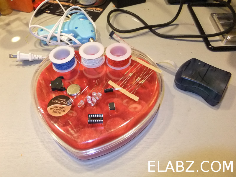
Oscillating POV display parts and tools
Here is a short video of the persistence of vision effect and the message programmed in the display. It is a bit easier to see it on a test circuit I built for easier programming and debugging. Also, in the final version of the software the heart symbol is actually filled in (as on the photos with the chocolate box) but the rest of the message looks exactly like you see on this video below:
The circuit schematics for this project is very similar to that of the previous two LED blinkers – the only difference of course is the amount of Charlieplexed LEDs – I figured 6 LEDs would have been enough for the simple message I wanted to show. This time I also decided to make a board for the project (see picture below), and BatchPCB is making it as I type this, but I have severely underestimated the time it takes to make and ship a PCB from China around the time of the Chinese Lunar New Year, so to build this project in time for Valentine’s, I had to revert back to the freeform PCB-less builts like the previous LED blinker project here and here
The circuit schematics and the board:
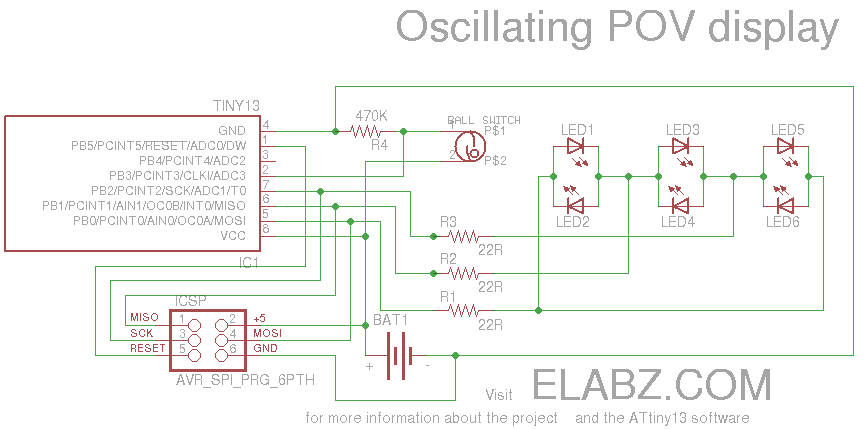
Oscillating POV display circuit diagram
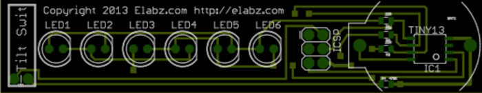
Attiny13 Oscillating POV display PCB
Building it
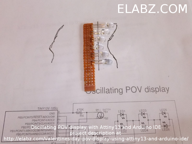
Mounting LED at proper height on the POV LED module

Complete LED strip module with current limiting resistors and other wiring
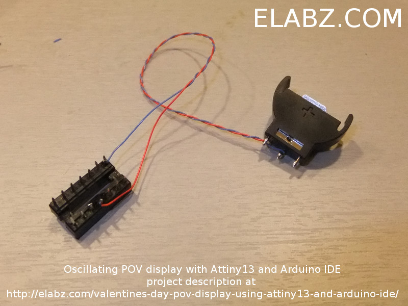
POV display wire MCU power from the battery holder
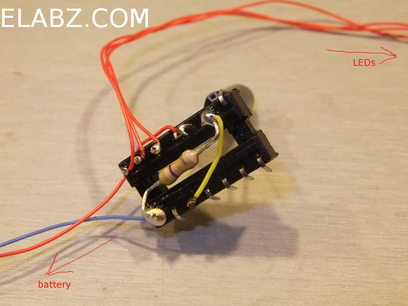
POV display MCU socket wiring
POV display position parts before gluing in place
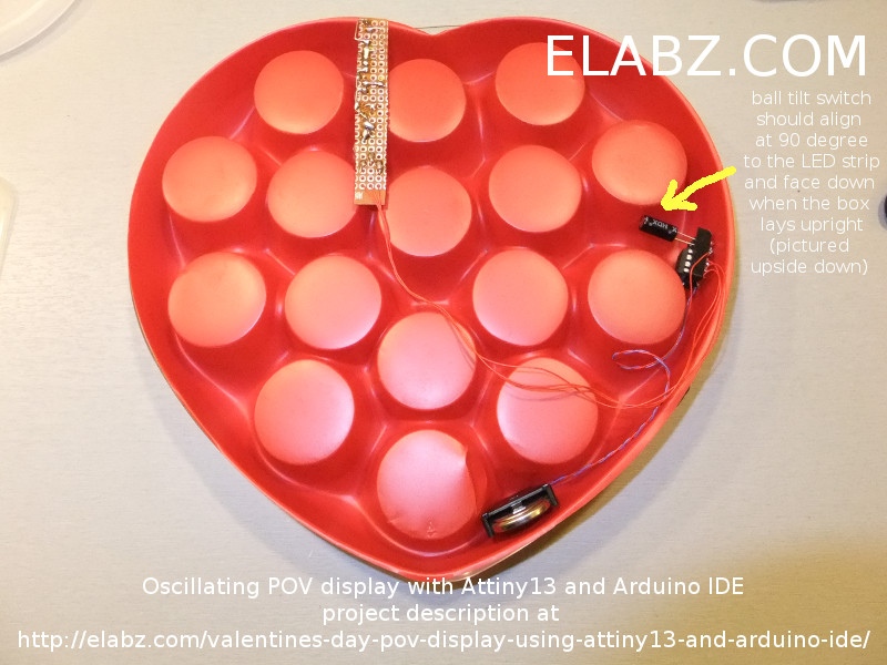
Also important is that the software times each scan of the message to the ball tilt switch closing event – because it’s an oscillating POV display (unless you can continuously rotate the box with your hand, it had to be!), you don’t want to show the message on the way back because it will be flipped horizontally (i.e. mirror image). Because all three symbols used – I, ❤ and U are all symmetrical, perhaps it would not be too bad to show a message that would read something like I ❤ U U ❤ I – sounds rather sweet (although does not make sense grammatically) – but I wanted a more universal display that could show some other symbols, too, and those may not be symmetrical. So the software uses the ball tilt switch to watch for the proper direction of the swing and so the ball switch should be facing toward the direction in which the message will be shown – i.e. to the right hand side when the box is upright. Note that on the pictures it’s upside down – just to eliminate any confusion.
When you are gluing the battery holder in place, keep in mind that you may want to change the battery in the future, so leave the top opening of the battery clear of any glue residue. Same goes for the ATtiny13 – you may want to avoid gluing it permanently just in case you need the chip in the future. Use only low temperature hot glue sticks or the glue may melt the thin plastic liner.
When you’re done with the hot glue, flip the box over, load with chocolate and give it to someone who deserves it!

POV Display Ready
A small note on actually using the device – the software is trying to find the average duration of the swing (back and fourth) and starts the scan after 1/8th of the complete cycle has passed since the ball switch had its contact closed (and de-bouncing time expired) i.e. 1/4th of one forward swing, which was my crude attempt at centering the message inside the width of your swing. This works when you’ve already moved it back and forth three-four times but it may make the first couple of swings look weird (squished) – that’s because the average time has yet to calculate properly. Since it starts from zero, it needs a few iterations to resemble the actual average.
Several things could have been done to alleviate this issue but I have hit a very hard limit in ATtiny13 – the amount of flash memory available for the program. The sketch below compiles to 1006 bytes and ATtiny13 can only keep 1024, so I was really counting individual bytes here and could not avoid the issue of average swing duration. Once something crude and simple like what’s in there could actually fit into the memory. I would be delighted if someone takes the hardware and this early version of the software and comes up with a way to pretty the display a little – and finding the proper time to start the scan every time is the first issue I would start looking at if you want to improve the project.
As I mentioned, the sketch uses up 1006 bytes out of 1024, and so we can fit 18 more lines of scan in there which can enable slightly longer messages, such as I ❤ NYC and perhaps even I ❤ BEER. Not sure about the latter, but I tried to fit my wife’s name in there (5 letters) and couldn’t, so I just stopped trying. But if you’re looking for more like St. Patty’s type display than St. Valentine’s :), you can easily replace red LEDs with green and try to spell I ❤ BEER following the easy coding instructions in the comments to the sketch – do let me know if it worked! 🙂
If you need help loading Arduino sketches into ATtiny13 MCUs, see this post on using Attiny13 with Arduino IDE here.
 Arduino Sketch for Charlieplexing_Tiny13_POV_6_LEDs and Eagle schematics and board files
Above is the zipped sketch and supporting Eagle schematics and board files (note that I haven’t received the boards yet so it’s not yet a proven design). And here below is the listing of the sketch’s C program – please read the comments for any customization ideas (such as those other messages for example). If you end up making your own version of this project, I would be delighted to see it! Please be sure to contact be or post a message in the Projects board of the forums.
/*
  Program code for the Pimp Your Chocolates project.
  Charlieplexing 10 LEDs mounted into a chocolate box using ATtiny13 with some brightness control using pseudo-PWM

  The tilt switch motion sensor is connected to Pin 2 (PB3)
  See http://elabz.com/valentines-day-pov-display-using-attiny13-and-arduino-ide/
  for the complete circuit schematics

  Code by Elabz.com
  http://elabz.com/
  This example code is in the public domain. If you end up using it in a project, please drop me a message, I'd be happy to
  know it was of some use. I'll also be happy to feature your project on my site, so send some pictures, too.

  LED hookup can be gleaned from the bitmap[] array values. For example, first LED's value is B00000001 which means that
  to light the LED the D0 has to ho HIGH and D1 - LOW, so the LED's anode is facing D0. LED #2 is between the same legs but in reverse.
  LED #3 is between D0 and D2, LED #4 is the same legs but in reverse and so on.

//       ATMEL ATTINY13 / ARDUINO
//
//                 +-\/-+
// ADC0 (D 5) PB5 1|    |8 Vcc
// ADC3 (D 3) PB3 2|    |7 PB2 (D 2) ADC1
// ADC2 (D 4) PB4 3|    |6 PB1 (D 1) PWM1
//            GND 4|    |5 PB0 (D 0) PWM0
//                 +----+


 */
#include <avr/pgmspace.h>

#include <avr/sleep.h> // sleep code by insidegadgets.com
#ifndef cbi
#define cbi(sfr, bit) (_SFR_BYTE(sfr) &= ~_BV(bit))
#endif
#ifndef sbi
#define sbi(sfr, bit) (_SFR_BYTE(sfr) |= _BV(bit))
#endif


byte bitmap[] PROGMEM ={0B00000001,0B000000010,0B00000010,0B00000100,0B00000100,0B00000001};
byte outModes[] PROGMEM ={0B00000011,0B00000011,0B00000110,0B00000110,0B00000101,0B00000101};


PROGMEM byte column[17]   = {

  33,    // --X----X // 0
  63,    // --XXXXXX // 1
  33,    // --X----X // 2
  0,     // -------- // 3
  24,    // ---XX--- // 4
  60,    // --XXXX-- // 5
  30,    // ---XXXX- // 6
  15,    // ----XXXX // 7
  30,    // ---XXXX- // 8
  60,    // --XXXX-- // 9
  24,    // ---XX--- // 10
  0,     // -------- // 11
  62,    // --XXXXX- // 12
  1,     // -------X // 13
  1,     // -------X // 14
  62,    // --XXXXX- // 15
  0      // -------- // 16

};

//byte d=HIGH;
byte y;
byte x;
byte z=1;
byte ledDelay=1; // microseconds to show one LED
unsigned int showTime=10000;
byte debounceDelay = 50000; // microseconds
byte p=LOW; // last state
unsigned int swingTime;
unsigned int swingTimeAverage;
unsigned int swingDelay;
unsigned long swingDelayNow;
unsigned long swingTimeLast;

void setup() {
// pinMode(3, INPUT);
//  sbi(GIMSK,PCIE); // Turn on Pin Change interrupt
//  sbi(PCMSK,PCINT3); // Which pins are affected by the interrupt
swingTimeLast =  millis();
}

void loop() {
unsigned long showNow;
unsigned  long periodNow;
unsigned  long lastDebounceTime;
byte currentColumn;
byte currentLED;
byte mask=1;

showNow = millis();
while(millis()-showNow < showTime)
{

int readNow=digitalRead(3); //
if(readNow != p)
{
  lastDebounceTime = micros();

}

  if ((micros() - lastDebounceTime) > debounceDelay) {
    // whatever the reading is at, it's been there for longer
    // than the debounce delay, so take it as the actual current state:
    //DDRB = 0B00000000; // turn everything off
    p=readNow;
if(p==HIGH){ // show symbols only on one way
  y=0;

if(z==0){

 delay(swingDelay);  // delay showing because the beginning of the cycle is where the symbol does not look right (speed to slow)
  while(y < 17){
      x=0;
      currentColumn = pgm_read_word_near(&(column[y]));
      mask=1;
      while(x<6){
         if(currentColumn & mask){
         PORTB = pgm_read_byte(&(bitmap[x])); // turn LED on
         DDRB = pgm_read_byte(&(outModes[x]));
         }else{
         DDRB = 0B00000000;
         }
        if(micros()-periodNow > ledDelay)
        {
        periodNow = micros();
        x++;
        mask <<= 1;
        }
      }
    y++;
  }
DDRB = 0B00000000;
  swingTime = millis()-swingTimeLast;
  swingTimeAverage = (swingTimeAverage+swingTime)/2;
  swingDelay=swingTimeAverage/8;
  ledDelay = swingTimeAverage/4; // this only works because ledDelay is in microseconds, so it's
  swingTimeLast=millis();

}
z++;

//}
} else {
  z=0;

}

}
  //    DDRB = 0B00000000; // dont show anything on the way back else it will be mirrored!


}

 DDRB = 0B00000000; // turn everything off at the end of the show
 sbi(GIMSK,PCIE); // Turn on Pin Change interrupt
 sbi(PCMSK,PCINT3); // Which pins are affected by the interrupt
 system_sleep();


}

// From http://interface.khm.de/index.php/lab/experiments/sleep_watchdog_battery/
void system_sleep() {
  cbi(ADCSRA,ADEN); // Switch Analog to Digital converter OFF
  set_sleep_mode(SLEEP_MODE_PWR_DOWN); // Set sleep mode
  sleep_mode(); // System sleeps here
  sbi(ADCSRA,ADEN);  // Switch Analog to Digital converter ON
}

ISR(PCINT0_vect) {

}
Looks awesome.
Not sure where to get a ball tilt switch though.
byte debounceDelay = 50000; // microseconds
uhh… Not sure what to make of that
I got the first one from a Brita (or was it PUR?) water filtering jar. It was used for counting tilts of the jar when you pour water to tell when the filter needs changing. Then eBay of course. $0.50 each from China.
Re: byte debounceDelay = 50000; // microseconds good catch! I wonder if it assigned 255 or 0 due to wrong type? I’ll go change it to int and see what happens. I have a feeling I’m going to need 5,000 mks (5ms) for debouncing not 50,000 if even that.
[…] Patrick’s Day is coming up and I thought it’s already time to update the original Valentine’s Day POV display with a new message and make use of the second PCB I had done at BatchPCB. Also, fortunately, John […]
Hi,
Please help me!
I’m trying to use this project to win my girlfriend’s love back. It’s very important to me!
I’m getting this error when compiling:
Arduino: 1.5.4 (Windows NT (unknown)), Board: “Arduino Leonardo”
Charlieplexing_Tiny13_POV_6_LEDs_final.ino: In function ‘void loop()’:
Charlieplexing_Tiny13_POV_6_LEDs_final:161: error: ‘GIMSK’ was not declared in this scope
Charlieplexing_Tiny13_POV_6_LEDs_final:161: error: ‘PCIE’ was not declared in this scope
Charlieplexing_Tiny13_POV_6_LEDs_final:162: error: ‘PCMSK’ was not declared in this scope
This report would have more information with
“Show verbose output during compilation”
enabled in File > Preferences.
Filipe, I feel your pain. I’ll try to help you achieve your noble goal!
The errors you are seeing are the result of the missing sleep.h library or a missing reference to it. Basically, it’s a part of the code that makes the ATtiny go to sleep after the display has been laying still for awhile. You can do away with these functions and simply make it always On or add a power switch into the circuit but I don’t see a reason why not just make the MCU go to sleep by itself. I just picked up the display I put a new battery into back in February 2013 and didn’t touch since, and it’s still alive and working!
Anyway, I’m not sure if Arduino IDE 1.5 still has the sleep.h library for sleep functions (I’m still on 1.0.2), and I hope it’s still there, so make sure this part of the code is not commented out:
It’s lines 32-38 in the original code
Hope this helps, let me know if it’s still a no-go. The issue may be with a different name of the library (unlikely tho) – I will have to get the proper version of the Arduino IDE to investigate further.
Good luck!
“Please help me!
I’m trying to use this project to win my girlfriend’s love back. It’s very important to me!”
Oh yikes!
“Arduino: 1.5.4 (Windows NT (unknown)), Board: “Arduino Leonardo””
This code is written for an Attiny13. You are compiling for an Arduino board.
Is that deliberate? If so, you will need to mod the code to run on a Arduino board.
I’m new to this. Can you help me step by step?
I bought an arduino leonardo 3 weeks ago. This week I found out your project and tried to get all the components at the local electronic’s store. I couldn’t get the attiny13 nor the ball switch. Instead I got the attiny85 and a mercury switch. I also have the avrisp mk2.
Now I have the IDE 1.0.2 since that’s the one you use. Next, I add the hardware folder to the sketchbook folder with the attiny85 folder inside. The attiny85 is detected, but I’m getting a new error: ‘byte’ does not name for a type. What can do to fix this? 🙁
I really don’t I have much time to put this together. Your help is much needed!!!!
Thank you for your fast reply!
You can change byte to unsigned char
Can you please post the changes in the code? I also new to programming.
Filipe, are you sure you’ve installed support for Attiny85 properly? It has its own core, different from smeezeklitty’s Attiny13 I used here, so you will need to follow procedure from here: http://hlt.media.mit.edu/?p=1695 to properly install support for Attiny85. Good news though – I don’t think any changes to the code are actually needed, as long as Arduino IDE knows how to handle the actual chip being used. I don’t think I have an 85 in my stash at the moment, so can’t really help in debugging the code on it, but, again, I don’t anticipate any changes to the code.
One other note: be careful with that mercury switch! In order for the image to show well, you need to shake the board rather vigorously (see videos) and the mercury switches I’ve seen look a bit too unsafe with a pretty heavy chunk of mercury bobbling about in a glass vial. Spraying your gf with mercury from a broken vial will not be very conducive to patching up the relationship. I would simply forgo the switch and make the program loop indefinitely instead of responding to the interrupt.
Hi,
Thank you very for the help you been giving me! I was using old MIT’s core. That was getting me into errors when compiling. After several hours trying to make the programmer work on Windows8, I connected the programmer to the attiny85 as shown it your schematics, but it took 25 minutes to upload the code. The attiny85 was set to run at 1MHz. Can the upload process be faster or am I doing something wrong? I made the board and mounted the components. If hold the board by the battery side the characters appear upside down and backwords. Can you tell what changes I have to do in the code to fix this?