ATtiny13 12-LED blinker with motion detection and scripted blinks
{adinserter Internal_left}
I can hear you screaming:”Not another LED blinker!” and yet here it is, packaged into yet another transparent Ferrero Rocher chocolate box, just like the first one. Why another ATtiny13 LED project? I needed to change the software to add a new feature and I had another box stashed away after Christmas – that alone should have been a reason enough 🙂 Additionally, I have to admit right here that there will likely be one more post that includes an ATtiny13, LEDs and chocolates before I let it go (soon, I promise) and move onto more serious things, such as the DVD-CNC project that’s been languishing on and off my workbench for more than a year now.
That said, if you are still interested in programming ATtiny13 with the Arduino IDE to blink 12 Charlieplexed LEDs, respond to motion (shaking) and have the LED on/off sequence scripted in an orderly fashion rather than random or simply 1 through 12, then read on!
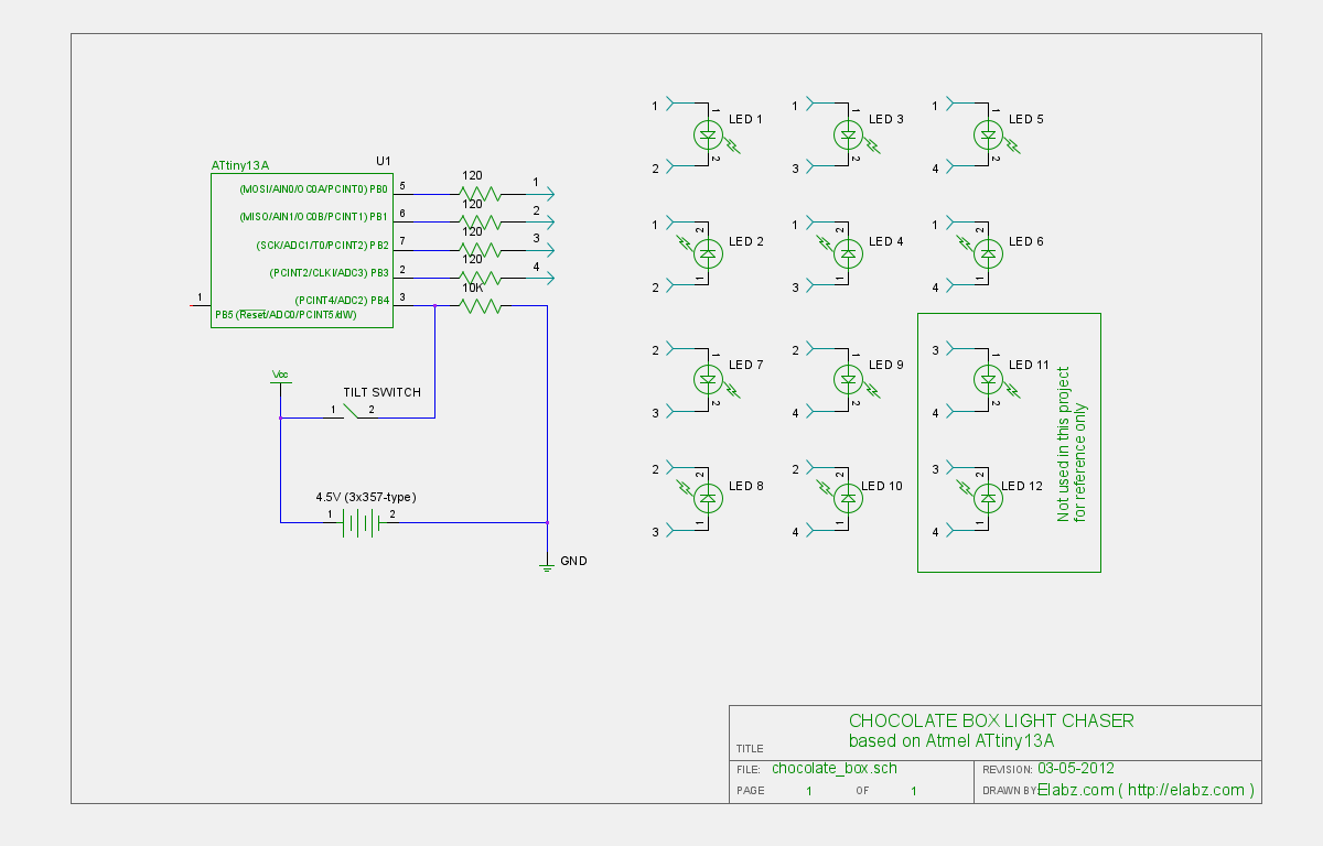
Circuit schematics for the ATTiny charlieplexed LED chocolate box project
The construction of the project is slightly different this time, too. I had a number of SOIC SMD-type ATtiny13 chips that I wanted to use and the much smaller SMD package looked much more appropriate for the project. Additionally, since I built the first chocolate LED blinker, I’ve stocked up on 3V battery holders – the part that was holding me back at the time – and wanted to use 3V power here.

All parts for the ATtiny13 12-LED blinker project
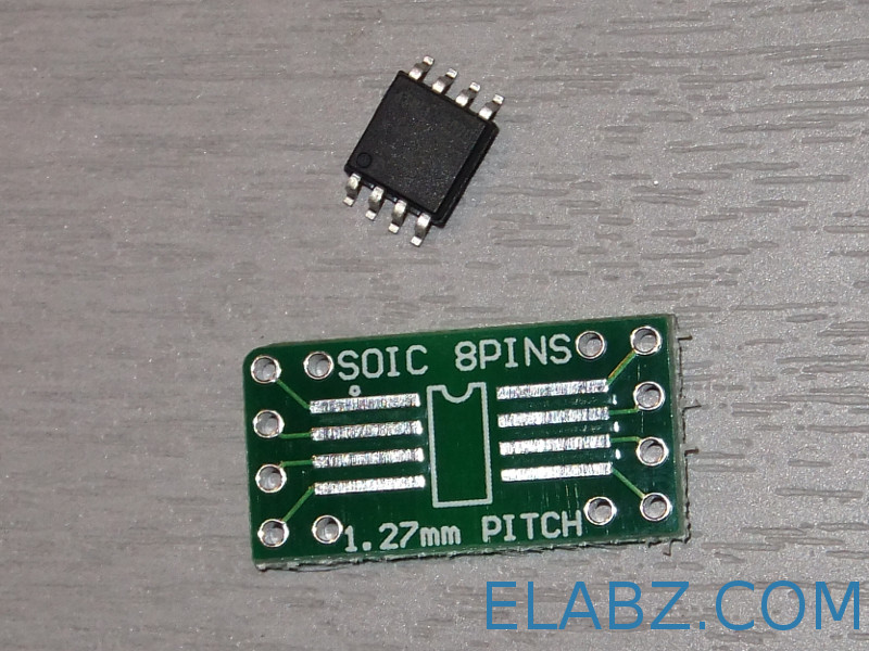
Mount Attiny13 onto the carrier board
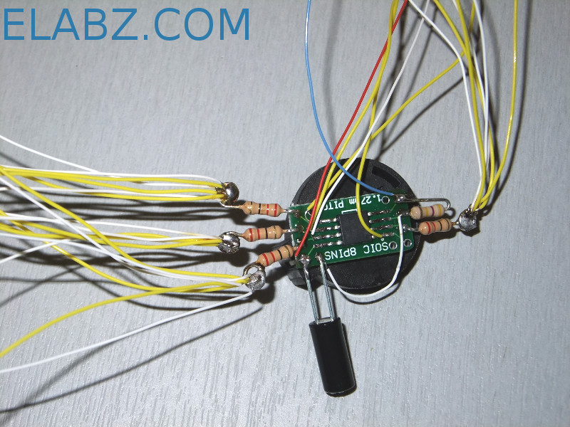
Circuit is built around the ATtiny13 mounted on the SMD adapter
An obvious part missing on this photo are the 12 LEDs prepped with 10″ lengths of 30AWG wire. I used white/yellow color coding to indicate the LED’s anodes and cathodes. White/Yellow blended it nicely with this particular box’es color scheme. If you use a different box, you may need to use different color wires. There’s a lot of wiring in this box and it tends to spill over. Since the box is transparent, you don’t want too much of the wiring to show.

Top of the box – best place to house the circuit

Glue LEDs in place using low temp hot glue
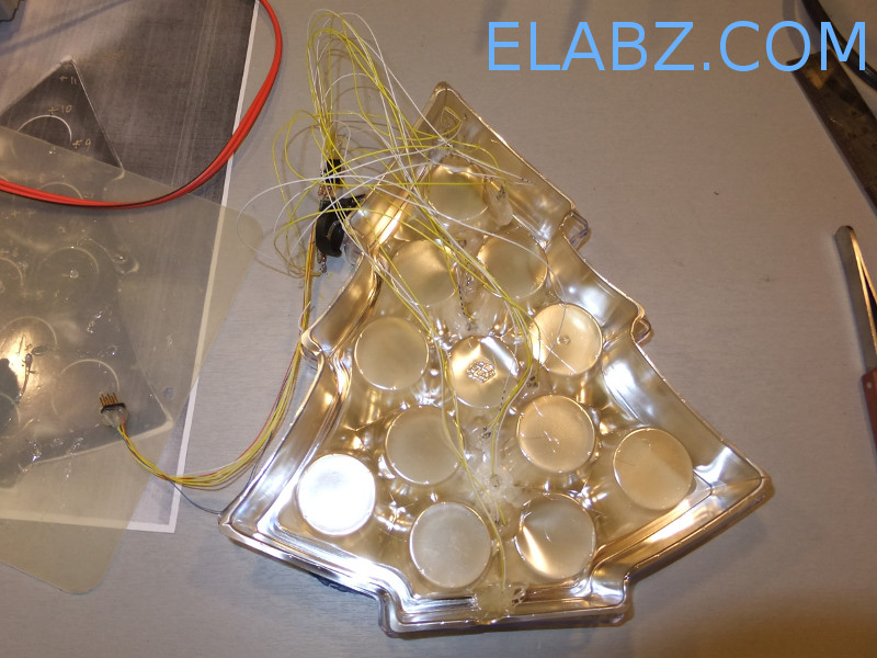
all LEDS are in place, ready for programming
 Arduino Sketch for the ATtiny13 12 LED blinker project
Here is the sketch in a file or just copy and paste from the program listing below. Please read the commentary inside the program for the way to write the blink scripts. There’s still about 120 bytes of memory remaining in the ATtiny13 which will be good for describing 60 more LED blinking steps. The highlighted part of the code is what defines the state of each LED (1=ON, 0-OFF) and the duration of the particular step.
0B0100100000000001 – here the LED1 (“1” on the right) and LED12 (“1” on the left of the 12 least significant bits) are ON
The 4 most significant bits are multiplied by the duration of one “clock” – 10 ms default. You may want to try defaults and then adjust to your own taste as needed:
0B0100100000000001 – 4 * clock (10 ms) = 40 ms
/*
  Program code for the Pimp Your Chocolates project Version 2.
  Charlieplexing 12 LEDs mounted into a chocolate box using ATtiny13

  The tilt switch motion sensor is connected to Pin 3 (PB4)
  See http://elabz.com/pimp-your-chocolates-with-arduino-ide-and-attiny13/
  for the complete circuit schematics

  Code by Elabz.com
  http://elabz.com/
  This example code is in the public domain. If you end up using it in a project, please drop me a message, I'd be happy to
  know it was of some use. I'll also be happy to feature your project on my site, so send some pictures, too.

  LED hookup can be gleaned from the bitmap[] array values. For example, first LED's value is B00000001 which means that
  to light the LED the D0 has to ho HIGH and D1 - LOW, so the LED's anode is facing D0. LED #2 is between the same legs but in reverse.
  LED #3 is between D0 and D2, LED #4 is the same legs but in reverse and so on.

//       ATMEL ATTINY13 / ARDUINO
//
//                 +-\/-+
// ADC0 (D 5) PB5 1|    |8 Vcc
// ADC3 (D 3) PB3 2|    |7 PB2 (D 2) ADC1
// ADC2 (D 4) PB4 3|    |6 PB1 (D 1) PWM1
//            GND 4|    |5 PB0 (D 0) PWM0
//                 +----+


 */
#include <avr/pgmspace.h>

#include <avr/sleep.h> // sleep code by insidegadgets.com
#ifndef cbi
#define cbi(sfr, bit) (_SFR_BYTE(sfr) &= ~_BV(bit))
#endif
#ifndef sbi
#define sbi(sfr, bit) (_SFR_BYTE(sfr) |= _BV(bit))
#endif


byte bitmap[] PROGMEM ={0B00000001,0B00000010,0B00000001,0B00000100,0B00000001,0B00001000,0B00000010,0B00000100,0B00000010,0B00001000,0B00000100,0B00001000};
byte outModes[] PROGMEM ={0B00000011,0B00000011,0B00000101,0B00000101,0B00001001,0B00001001,0B00000110,0B00000110,0B00001010,0B00001010,0B00001100,0B00001100};

PROGMEM prog_uint16_t column[]   = {
0B0111000000000001, // LED #1 ON, all others OFF , duration of this step is 7 ticks (7 x oneTick) (duration = 4 most significant bits)
0B0111000000000011,
0B0111000000000111,
0B0111000000001111,
0B0111000000011111,
0B0111000000111111,
0B0111000001111111,
0B0111000011111111,
0B0111000111111111,
0B0111001111111111,
0B0111011111111111,
0B0111111111111111, // All 12LEDs lit
0B0111101000000001,
0B0100100100000001,
0B0100100010000001,
0B0100100001000001,
0B0100100000100001,
0B0100100000010001,
0B0100100000001001,
0B0100100000000101,
0B0100100000000011,
0B0100100000000001  // LED #1 and #12 are lit, duration 4 ticks
};

boolean d=true; // direction forward=true
byte oneTick = 10;
int columnDelay; //5ms width of the column and space between them
int showTime=15000;
byte cycles;
byte ticks;
void setup() {
  sbi(GIMSK,PCIE); // Turn on Pin Change interrupt
  sbi(PCMSK,PCINT4); // Which pins are affected by the interrupt
  cycles = sizeof(column) / sizeof(int);
}

void loop() {
unsigned long showNow;
unsigned  long periodNow;
int currentColumn;
DDRB = 0B00000000; // turn everything off right after the MCU is awakened
start_show(); // turn on all LEDs one by one BEFORE the scripted animation starts.
//You can remove the start_show() function and use the space for several dozen more scripted steps instead

showNow = millis();
while(millis()-showNow < showTime)
{
  for(byte x=0; x<cycles; x++){ // counter for the columns
      currentColumn = pgm_read_word_near(&(column[x]));
      ticks = currentColumn >> 12;
      columnDelay = ticks * oneTick;
      periodNow = millis();
      while(millis()-periodNow < columnDelay)
       {
       show_column(currentColumn);
       }
       DDRB = 0B00000000;
       //delay(columnDelay);

  }

}

    DDRB = 0B00000000; // turn everything off at the end of the show

    system_sleep();


}
void show_column(int currentColumn){
  int mask=1;
  for(byte j=0;j<12;j++){ // bit shift the column to light up each individual LED
      if(currentColumn & mask){
      DDRB = 0B00000000; // turn everything off
      PORTB = pgm_read_byte(&(bitmap[j])); // turn LED on
      DDRB = pgm_read_byte(&(outModes[j]));
  }else{

     DDRB = 0B00000000; // turn everything off

  }
    delayMicroseconds(250); // give each LED a chance to shine
    mask <<= 1;
  }
}
void start_show(){
  for(byte j=0;j<12;j++){
      DDRB = 0B00000000; // turn everything off
      PORTB = pgm_read_byte(&(bitmap[j])); // turn LED on
      DDRB = pgm_read_byte(&(outModes[j]));
      delay(25); // give each LED a chance to shine
  }
   for(byte k=12;k>0;k--){
      DDRB = 0B00000000; // turn everything off
      PORTB = pgm_read_byte(&(bitmap[k])); // turn LED on
      DDRB = pgm_read_byte(&(outModes[k]));
      delay(25); // give each LED a chance to shine
  }

}
// From http://interface.khm.de/index.php/lab/experiments/sleep_watchdog_battery/
void system_sleep() {
  cbi(ADCSRA,ADEN); // Switch Analog to Digital converter OFF
  set_sleep_mode(SLEEP_MODE_PWR_DOWN); // Set sleep mode
  sleep_mode(); // System sleeps here
  sbi(ADCSRA,ADEN);  // Switch Analog to Digital converter ON
}

ISR(PCINT0_vect) {

}
Once ATtiny13 has been programmed, it should go through several cycles of blinks for the duration of the show set by this variable: showTime=15000; (15 seconds default) and then go to sleep until you shake the box again. Here is the video one more time that shows how the sketch above works:
I hope you enjoyed this latest installment in the LED blinker series of posts here, I’ll go on finish the third (and hopefully the last one on this blog) LED blinker project.
As always, if you have a question regarding the project, post it into the Forums, Help section. Blog comments at the bottom of this page are not as useful for the question/answer flow that may be needed to help you with your project as the forums.
Looks pretty neat.
Thanks, smeezekitty. I just love the little chip, can’t stop thinking about all the different ways to use it in projects. I got myself a couple of Attiny85s just in case I overgrow the 13th but I keep returning to the small ones anyway.
Thanks for stopping by,
Cheers!
What is the code size?
This particular 12-LED blinker code compiles into 900 bytes but each blinking step (I like to think of them as notes as in musical notes) will add 2 more bytes if you were to make a longer blink show. So you have about 60 more steps to animate your LEDs. Right now I’m working on another program that’s 1022 bytes – I am literally chasing every single byte here 🙂 I guess that’s what makes it so special – love a little challenge thrown in for more fun.
[…] « ATtiny13 12-LED blinker with motion detection and scripted blinks […]